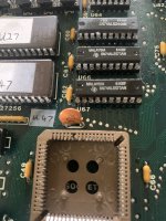
I noticed a missing plastic insulator leg in the CPU socket (see photo):-
Hi SteveG,
That is unfortunate to be missing that piece of socket plastic.
The pins in question are the READY and VCC pins.
Do be careful that the READY pin doesn't make contact with VCC or anything else, which could surely damage your 82284 controller chip. The READY pin is essential because it also determines your I/O and memory access timing since the READY signal serves to terminate the 286 command cycle in the PC/AT. The command cycle is when the CPU is actually performing the data read or write action it set out to do in that CPU state sequence.
If the READY pin is not connected with the 286 CPU, or shorted to something, your CPU will not do anything anymore, which is important to know.
I read this thread of yours today and I have a few more things to add, besides all other things already mentioned.
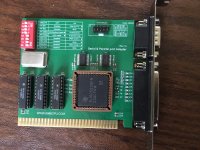
I have built a 286 system similar to the 5170 and I have tested a few similar "chipset-less" mainboards from several manufacturers.
What I can tell you from my own experience is that the COM port support is very poor with various BIOS types I have tested so far in these types of systems.
The AT BIOS tests for the COM port being present, and saves the detection in the CMOS RAM, as mentioned. Based on this "present" or "not present" status that the BIOS detected and saved in the CMOS RAM previously, you may or may not have a working COM port generally in DOS. And this detection process is not a perfect thing as I have seen in my tests.
The 16 bit AT is substantially different from the XT in that the timing is much more delicate and sensitive.
The reason for this is that the AT contains a backward compatibility mechanism with 8 bit hardware, invented by IBM. Which is exactly the situation with your COM port because it only uses 8 data bits. In an XT we connect directly with these 8 bits, however the XT can also have trouble with COM ports, but I won't get into that now since that's not the issue. In general, I have experienced various issues with a COM port both in 8 and 16 bit systems.
Added to this fact is one other thing, your 5170 is one of the most early systems of its type which, even though it is in my opinion an amazing design and concept which deserves appreciation, since it's a first system of this type, it is also at the same time not a "perfect" machine yet. In my testing experience I have seen many situations where the CMOS RAM got corrupted, resulting in all sorts of strange behaviour. So if you see anything funny, it would be good to clear the CMOS information. What I am doing lately is to use a DOS CMOS backup program to store a known good CMOS content in a backup file, and if the CMOS RAM is acting up, I simply read back the known good copy. This solves a lot of issues that I have experienced, and enabled me to have less trouble during all of my test work.
When your mainboard left the IBM factory built into a system, it had been assembled in a known good configuration of all the components on the PCBs and it had been quality tested etc.
The problem for example may be that after leaving the factory, the mainboard may have been repaired and certain ICs may have been replaced. And if a repair was done for example by a person not working for IBM at the time, and a certain IC was replaced with one that does not exactly match the logic type and timing specs of the replaced IC, this can potentially introduce timing changes which may mess up the perfectly working mainboard timing as verified by IBM. So in such a situation, the mainboard may no longer be functioning exactly the same way as when it left the factory. If you see evidence of repairs on the bottom of the mainboard, I would look at the IC in question very carefully and try to find a photo of your mainboard version to see if you can find a mostly identical photo to your mainboard where you can see mostly the same ICs in various places, to know:
- brand
- logic type
- year/month of manufacturing
of the replaced IC.
If your mainboard is 100% factory that would be the best situation really.
All these things could matter in certain sensitive circuit areas if the IC is too far off compared to what IBM put in at the assembly line. I am not saying it's the case here, however you may benefit from keeping this point in mind at some time when doing a repair or test and seeing unexpected results for which you can't find an explanation since there appears nothing faulty anywhere.
Okay, back to the COM port problem. If the BIOS doesn't detect the COM port, it may still be perfectly functional (!). So don't get too much distracted by the fact that the port is not working, it may be the AT BIOS which is the actual problem causing this issue. Especially since you verified the serial port card to be working in another system. So the ICs on the card are all fine.
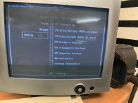
So what I advise you, if you have the possibility to try this, is to use the Quadtel BIOS which is suitable for the IBM 5170. The Quadtel BIOS is much improved compared to all other BIOS I have tested, in that it consistently keeps detecting the COM port correctly. So if you are able to change the BIOS, I can highly recommend, at least for testing purposes, the
Quadtel BIOS from minuszerodegrees.net.
A way of testing this out, whether you have this BIOS detection issue, is by starting windows.
I am not sure, but I think at least from windows 3.0 onward, or from windows 3.1 onward, it contains its own mouse support and doesn't care whether the BIOS saw a COM port. The mouse pointer will still work in windows no matter what the BIOS is seeing or not seeing.
Also it may be possible to make mouse support "appear" on a COM port when running MSD diagnostics from DOS 6.22. I have seen the mouse working in MSD and not in DOS, for example.
So it depends on what you are able to test in your system.
Also I want to add one more thing, if one serial port card seems to be not working in your 5170, and works in another system, it may very well not matter which type of serial card you test out, they may possibly all not be working, no matter being a card with a separate UART IC, or a multi-I/O card containing a single chip which does multiple interfaces, and contains the serial port as well.
So if you can somehow verify that at least you don't have this BIOS related issue I described, I would do that first or you may be doing a lot of work to try to fix something which is structurally not working reliably.
So the best test would be the Quadtel BIOS. If using that you still are not able to get the COM port working, in that case it must be a different issue then.
I hope you can find some way to continue your work on the system, do be careful not to short the READY pin of the socket to anything else.
Another thing I want to share is when I was testing with MR BIOS, it also had trouble seeing the COM port at times. I solved this problem by powering on the system first without the COM port, then power off, and power back on with the COM port added again. These differences when power cycling may trigger a detection, at least in the case of MR BIOS.
One other thing may be the RESET input on the UART chip, if that RESETDRV line on the ISA slot is very noisy due to crosstalk in the PCB, it may prevent the COM port from working properly. This may be resolved by putting a 2.2nF capacitor between RESETDRV and GND, preferably at the most outer slot right next to the edge of the mainboard. What I also have done at one time is to disconnect the UART RESET pin from the RESETDRV and connect it directly with GND. That also solved the problems I experienced that time.
Kind regards,
Rodney