falter
Veteran Member
I decided to do this as a separate thread from my original post in Other because I have what I need now and am proceeding.
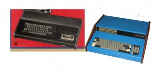
Anyway, a background. I've for years known the basic story behind the Sol 20, and had been under the impression that it evolved from what was originally envisioned as a terminal (hence its name). I had never seen the pure terminal version nor bothered to look up the original article that introduced it. I simply stumbled onto it one day and saw the front cover of Popular Electronics, July 1976 and saw a prototype-looking unit with a keyboard that looked suspiciously like one I had. Sure enough, it more or less was. I started reading more and of course, later, found the artwork for the original motherboard. I became really intrigued at that point because the motherboard clearly looked set up to do more than mere terminal duty - it had multiple ROM sockets and an S100 connector. I then read that Processor Tech essentially called it a terminal to deke around Popular Electronics' reputed ban on new projects involving computers (I don't know if that's true or not). I did find it interesting how the 'optional' ROMs were mentioned in the article with little or no explanation about what they did. Had a definite cloak and dagger feel!
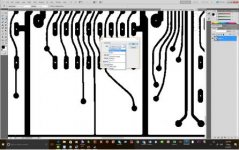
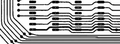
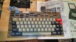
Naturally once I realized I, again, had the correct keyboard to build a replica of an important prototype, I put it on my future project list. Now, looking at the artwork, I expect it to be extremely challenging. The only copy of the artwork I've found is messy, to say the least, and that particular design is reputed to be unfinished/unworkable. Reputed.
And this is where the story gets kind of convoluted. Was this 'prototype' a one off to herald the arrival of the eventual Sol-20? The article advertised boards for sale, in addition to the artwork provided in a construction guide you could mail out for. I've never seen and have not been able to find any pictures or auctions or anything in private collections I'm aware of that shows that first design board made it into the hands of the public. But if they were selling plans, you'd assume probably at least some did.
Anyway, to resolve the matter I decided to try emailing the designer, Lee Felsenstein. I didn't expect him to answer, being (I'm sure) a busy guy and a bit famous and probably not having time to answer queries from some random stranger about work from 40 years ago. But to my delight, he did answer. My questions to him were: what were the ROM sockets for? Could you run CONSOL or SOLOS on this board? Was this purely a 'terminal' or was it a computer from the start? Did any get built beyond the cover unit? And where is the cover unit?
I asked a lot more politely than that of course. Anyway, Lee very generously answered, and his answer leaves a few more question marks. He said the unit that appeared on the cover of PE was indeed a prototype of what would become the Sol-20. Without confirming or denying that the ROM code for SOLOS worked on that unit, he simply said the ROM code was printed in the manual. He said the prototype cover unit still exists and is owned by Bob Marsh. The tape deck seen was non-functional, and that only two boards were made -- the one in it, and a unit he has that required some 100 wires to work. He did not indicate if any of those first design boards were sold. I did ask but did not receive a response in a second email and declined to pester him further. To read what he said over again, it sounds like this was a prototype that was a one off, and it almost sounds like whatever boards Processor Tech was providing were likely the boards used in the eventual Sol 20. But the thing that throws a spanner into that is that PT/PE were sending out construction guides with this first motherboard design. They advised it was complex and offered pre-made boards for those not skilled enough to fab one themselves. It doesn't make sense to me that they'd be shipping out artwork for one design and selling kit boards for another.
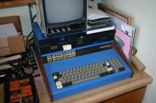
But anyway, there you have it. And it is my intention to build another copy of the prototype, someday. Certainly I can accomplish the case, keyboard, etc. To a degree -- there are no color photos of that unit. I don't know how to get in touch with Bob Marsh and I'm not sure if he'd want to share that info. But I'm imagining the case was probably 'IBM blue' like the later -20 and probably the wood is the same as the -20 also.
From there, recreating the board will be a huge challenge. As I said, the artwork is really messy, but I think it's salvageable. It would be a monumental task to line everything up perfectly (it is double-sided), but that's part of the fun. I never go into these things with unrealistic expectations. If I end up with a non-functional unit that *looks like* the prototype, I'm happy. If it works, what a great story, right?
For those curious - here is a link to the artwork: http://www.sol20.org/articles/img/PE_SOL.pdf Check out that S100 connector way off in the corner where it'd be kind of tricky to use in any sort of case.
Anyway, a background. I've for years known the basic story behind the Sol 20, and had been under the impression that it evolved from what was originally envisioned as a terminal (hence its name). I had never seen the pure terminal version nor bothered to look up the original article that introduced it. I simply stumbled onto it one day and saw the front cover of Popular Electronics, July 1976 and saw a prototype-looking unit with a keyboard that looked suspiciously like one I had. Sure enough, it more or less was. I started reading more and of course, later, found the artwork for the original motherboard. I became really intrigued at that point because the motherboard clearly looked set up to do more than mere terminal duty - it had multiple ROM sockets and an S100 connector. I then read that Processor Tech essentially called it a terminal to deke around Popular Electronics' reputed ban on new projects involving computers (I don't know if that's true or not). I did find it interesting how the 'optional' ROMs were mentioned in the article with little or no explanation about what they did. Had a definite cloak and dagger feel!
Naturally once I realized I, again, had the correct keyboard to build a replica of an important prototype, I put it on my future project list. Now, looking at the artwork, I expect it to be extremely challenging. The only copy of the artwork I've found is messy, to say the least, and that particular design is reputed to be unfinished/unworkable. Reputed.
And this is where the story gets kind of convoluted. Was this 'prototype' a one off to herald the arrival of the eventual Sol-20? The article advertised boards for sale, in addition to the artwork provided in a construction guide you could mail out for. I've never seen and have not been able to find any pictures or auctions or anything in private collections I'm aware of that shows that first design board made it into the hands of the public. But if they were selling plans, you'd assume probably at least some did.
Anyway, to resolve the matter I decided to try emailing the designer, Lee Felsenstein. I didn't expect him to answer, being (I'm sure) a busy guy and a bit famous and probably not having time to answer queries from some random stranger about work from 40 years ago. But to my delight, he did answer. My questions to him were: what were the ROM sockets for? Could you run CONSOL or SOLOS on this board? Was this purely a 'terminal' or was it a computer from the start? Did any get built beyond the cover unit? And where is the cover unit?
I asked a lot more politely than that of course.
But anyway, there you have it. And it is my intention to build another copy of the prototype, someday. Certainly I can accomplish the case, keyboard, etc. To a degree -- there are no color photos of that unit. I don't know how to get in touch with Bob Marsh and I'm not sure if he'd want to share that info. But I'm imagining the case was probably 'IBM blue' like the later -20 and probably the wood is the same as the -20 also.
From there, recreating the board will be a huge challenge. As I said, the artwork is really messy, but I think it's salvageable. It would be a monumental task to line everything up perfectly (it is double-sided), but that's part of the fun. I never go into these things with unrealistic expectations. If I end up with a non-functional unit that *looks like* the prototype, I'm happy. If it works, what a great story, right?
For those curious - here is a link to the artwork: http://www.sol20.org/articles/img/PE_SOL.pdf Check out that S100 connector way off in the corner where it'd be kind of tricky to use in any sort of case.
Last edited:

