• Please review our updated Terms and Rules here

TV Typewriter replica project back on track

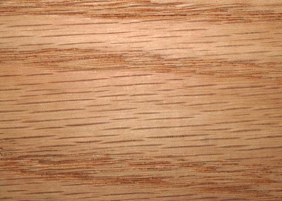
You're the third person to suggest oak to me. And it sure looked like oak on first blush, until I saw the side shot I posted above. I looked at Home Depot for half an hour and nothing really looked like Don's. The oak had a darker brown colour to it. The pine grain looked too wide.

The reason I'm inclined to believe pine is a) as others have noted, pine harvested 40 years ago is different than today and b) Don's whole thrust in this project was to keep the cost as low as possible. I don't know what oak and the like cost in the 1970s, but I know what it costs now and it seems like the Don thing to do would have been to go with cheap, aka pine. Then again, he knew this would be making an appearance in a magazine and elsewhere so maybe he went nicer.

I would say the sides on Dons are a bit fine grained for a Pine (usually deal in the UK). They look more like Oak skirting Board to me...

http://www.oakstoredirect.com/solid...d-edge-kiln-dried-20764-p.asp?variantid=20765
 
Also, if you look to oak (both red and white), you can see the fine "rays" that typify most species of quercus. I didn't see it in the photo sample, but that could be the fault of the photo itself.

images%5CQuercus%20falcata%5Cwood.jpg
 
First, can I suggest that on used what he had to hand. So if he had a bit of Oak, Ash or Elm he would have used that. Well, that's what I would have done!..
.. that last picture does look a bit like DEAL which as I said above is often sold as Pine in the UK, but of course it will almost certainly be an American wood.

As for the color wood changes with age. My kitchen table has a leaf which is kept out of sight. When I bought the table it matched the table. These days its a much lighter color. Really clashes.
 
Looking at the different photo, I'm still thinking fir for the sides (note on the visible side, the signs of the planer "bounce" as two light-colored lines. So we know that these were board ends.) The rest of it is definitely MDF with a paper overlay. I wonder if Don picked his wood up from the scrap bin of a cabinet shop.

You can get MDF in virtually any size, provided that it's ordered in quantity. I keep a few sheets of 3/4" MDF melamine-covered board around for making shop jigs and shelves. If you keep it dry and don't put too much weight on it, it's a nice inexpensive alternative to plywood and takes paint very easily. It is much heavier than plywood however. The overlay can be a simple paper, melamine, vinyl faux-grain or just about anything else.
 
I'm trying to figure out how Don got into it. There's no screws on the sides that I've seen, the back just has the three and the top appears to be permanently fixed there. Part of me is wondering if he mounted the boards upside down against the top and had access through the bottom. Regrettably nobody has shots of the bottom and the museum won't unscrew it from the display it's bolted to to have a peek.

On a more technical note -- here are the ICs I've amassed thus far, with dates:

(IC) (QTY REQD) (QTY ON HAND) (YEAR OF ACQUIRED IC)
7805 regulator 1 0
2524 Signetics 6 12 1980
7406 Hex driver 1
2518 hex register 1 10 1973
2513 char gen 1 2 1973
74165 PISO generator1 2 1973
7401 NAND 1 5 1974
MC4024 1 2 1973
8288 divide by 12 4 8 1973
7473 ttl 2 3 c 1973
7432 qua 2 0
7410 ttl 2 2 1973
7408 quad 1 1 1972
74197 ttl 4 0
7402 quad 2 5 c 1972
7474 flip 1 4 1973
7400 quad 1 1 1973
555 timer 1 5 1986

Haven't done too badly. I wish I could find 2524s that were correct vintage. The 7805 has me a bit confused. The 7805s I've seen online look like a square with three prongs coming out. But one I stumbled on looked like a metal can on a wide base. This is the parts placement diagram from the plans:

7805.jpg
 
That outline in the plans looks like a standard TO-220 package attached to a heatsink that has outrigger tabs like this. That's not a bad idea--it keeps the package leads from being flexed too much.

The AMD AM2807 is a plug-in substitute for 2524. Maybe that will expand your search a bit.
 
Okay so today I did a bit of shopping for what Don Lancaster called 'G-10 green' boards. I found some on ebay of various sizes and thicknesses, like this:

http://www.ebay.com/itm/375-X-5-5-X...Glass-Epoxy-/261421956643?hash=item3cddf67e23

What I'm wondering is if there is anyone here who could explain to me, in terms a baby would understand, how one goes from that to getting copper on there in the patterns provided by the magazine. I mean, I've done some reading on 'foil patterns', '4x tape'.. but I'm just not quite getting how it all works. And I'm wondering if in 2015 this process can actually still be done with equipment that a home user could affordably acquire.
 
The old hobbyist way (other than direct masking using tape and resist) was to use photosensitized board, which was a PCB with a photosensitive gelatine-like coating. You exposed the board to UV light or sunlight through the printed mask and then developed it using a special solution. There were both positive and negative processes, so you used either the conductor pattern printed in black or reverse. At any rate, what you got after developing was a board that had bare copper where it was to be removed and resist where the copper was to be preserved. Dunk it in an acid bath (usually ferric chloride) and wait for the copper to go away. Rinse and scrub the board clean and there you go. Kepro is a name of a one-time provider of PCB kits--I don't know if they're still in business. A detailed explanation as a lab exercise

After laser printers got to be available to the average consumer, things changed a bit. You could take your artwork and print it on old magazine clay-coated paper. You then "ironed" the paper to the clean PCB stock either with an ordinary clothes iron or a special tool made for library use, which would cause the ink to detach from the paper and stick to the PCB. Etch and rinse as usual. There are many sites on the web where this is detailed. Here's one.

I can attest that both methods work.

Of course, if you're a commercial operation routinely making prototypes, an in-house LPKF machine is very handy--if you have sufficiently deep pockets.
 
Ahhhhhh... thank you again Chuck. Now it's making sense. So essentially the process in 1973 is like what this fellow does. I don't know how I didn't find that video earlier but I did after googling photo-etching today. I just have to find G10 green stock with the photoresist stuff somewhere. I'm wondering if the artwork from those PDF pages posted by Matt Holley are good enough. He apparently has higher DPI scans of them but I tried contacting him with no success.

I suppose I'll have to decide if I want to leave the trace side of that artwork as is or wipe the SWTPC logo and stuff from it, since Don's prototypes (according to him) were before their involvement, just to be more prototypical. Really wish I could find a photo of the original boards. Very surprised nobody thought images of those would be valuable for posterity.

If I did go the 'keep the SWTPC flavour', my problem then is that I'd want to replicate the white silkscreening for parts placement on topside. And I have no idea if that's even possible in the home? Most of the silkscreening I've seen consists of printing in black toner in reverse and then transferring from paper via nail polish or something similar. But I'd like to have the white.
 
Last edited:
I'd be very surprised if Don didn't do the original S/N 1 in wirewrap. It was certainly a method of choice back then.

I asked Don about whether the prototype boards were different than the SWTPC ones. I thought I had asked if they were wire wrap but I can't find any evidence I did. But this is what he said:

The original boards were G10 green.
Original artwork was 4x tape and dots followed by litho camera reduction.
The boards were made, then tested and debugged, then corrected.

Any SWTPC involvement was much later.


So I guess the question really is, was the original artwork the basis for the SWTPC boards later? He never answered that unfortunately. He did however indicate that the MDS keyboard he used on the prototype was one of about 60 'they' purchased and rebuilt into 40 or so TVT keyboards. So it kind of sounds like there was some kind of production going on before SWTPC got into all of it. I'll have to keep hoping a picture surfaces somewhere one day.
 
Check out this page on Michael Holley's website - SWTPC TV Typewriter II - it's clearly a different design than the original Don Lancaster design.

http://www.swtpc.com/mholley/RadioElectronics/RE_CT_1024.htm

There is no reason not to think that the artwork in the original TV Typewriter construction article wasn't the "corrected" version of his original artwork, only reduced to actual size. If I was building one, I'd use the artwork from this article to do it.

http://www.swtpc.com/mholley/TV_Typewriter/TV_Typewriter_Reprint.htm

There were other vendors of TV Typewriter inspired designs. For instance, the Digital Group made at least two versions and the Apple 1's video section was largely inspired by the TV Typewriter. In short, the original article inspired a lot of derivations.

regards,
Mike Willegal


I asked Don about whether the prototype boards were different than the SWTPC ones. I thought I had asked if they were wire wrap but I can't find any evidence I did. But this is what he said:

The original boards were G10 green.
Original artwork was 4x tape and dots followed by litho camera reduction.
The boards were made, then tested and debugged, then corrected.

Any SWTPC involvement was much later.


So I guess the question really is, was the original artwork the basis for the SWTPC boards later? He never answered that unfortunately. He did however indicate that the MDS keyboard he used on the prototype was one of about 60 'they' purchased and rebuilt into 40 or so TVT keyboards. So it kind of sounds like there was some kind of production going on before SWTPC got into all of it. I'll have to keep hoping a picture surfaces somewhere one day.
 
Yeah the CT-1024 was an entirely different machine designed 2 years later by Ed Colle to get around the difficulty of finding certain semiconductors. I actually scored an original one on ebay a couple years back. Despite the fact that it doesn't work, it is by far my favourite collection piece.

The great thing about the TVT versus other 'replica' projects is that, provided you use original, period correct parts, it can be every bit as legit as one built in 1973. And I could totally use the magazine artwork and not affect that legitimacy. I just have to learn to suppress my railway modeller's instinct to get it *exact* and accept that, barring a photo surfacing, there's no way to really know what's in that prototype TVT case and likely never will be.

Besides, I have enough challenges ahead as it is. I opened up the MDS keyboard again and looked at the mass of wires I have to somehow connect to an as-yet unbuilt ASCII encoder. This is going to be interesting. :)
 
Okay so this weekend I'm going to work a bit on the keyboard situation, mainly to aid in finishing the case. As the case sits right now, the keyboard just barely squeezes into it. These MDS keyboards are almost like Lego -- the keys are square, and to fill in spots where there are no keys there are either 'blank' squares or half squares. Looking at Don's and mine (mine with the keytops mostly removed):
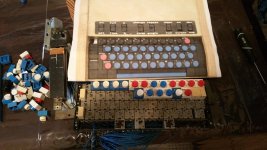
20151002_175158.jpg

My keyboard has approximately 12 keys per row. Don's has 11. Don apparently completely disassembled these keyboards, re-arranging them based on the colour of keytop he wanted. It appears the final pattern he has is very close to mine -- the space bar appears to be a half space to the left (or all the keys a half space to the right), the 12 keys removed and replaced by blanks, and a full row of blanks added on the left side. Based on what I can calculate, it works out to about the same width, maybe a half block wider. Now, as we can see with mine, the keys screw into these twin rails which are then slide locked into one another:
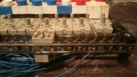
20151002_192325.jpg

Kind of cool -- I can sort of picture the Mohawk people assembling these according to each individual client's needs. The blanks I can replicate easily. I can even replicate the keytops, and will to have spares around or if some future TVT replicator wants them and can't find an original MDS keyboard.

What's unclear from photos of the prototype is how Don integrated the twin rails the keys lock into into the design. In this photo we can see a hint of a metal bracket appearing there. There's more of it exposed in this later photo:
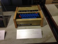
IMG_3539.jpg

It's not anything from inside the MDS keyboard I have. Some kind of custom bracket he used. I'm guessing left the outer lip of the MDS keyboard 'rails' sits just under it, and the right outer lip is recessed into the side of his case.

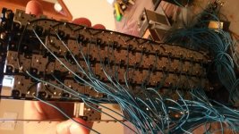
The other thing I'm confronted with is the wiring. As you can see, the keys are 'tied' to one another (black wires):
20151002_181106.jpg

My understanding is, based on both Don's words, these keyboards were wired for EBCDIC encoding, and needed to be completely rewired. Don mentions this in the second of these two articles on building encoders, the first an early version appearing before the TVT article:

http://www.tinaja.com/glib/rad_elec/ascii_encoder_4_73.pdf

And then an 'improved' one after:

http://www.tinaja.com/glib/impascii1.pdf

The first encoder article mentions the original 'low cost keyboard' Don devised in a previous article. He calls these simple "make" contact switches. I'm guessing that means the switches just completed a simple circuit when pressed, and presumably on the circuit board they took care of how the keys tied to one another, if at all.

Check out the picture on page 3 of the second encoder article. A keyboard just like the TVT's, keys configured exactly the same way. The metal brackets on the side look similar to what was exposed in the second photo, and I *think* he reused the rails the keys sit in, although that pic is poor quality. On the second last page, he specifically mentions these 'keypunch' keyboards, and details a bit of what I suspect he did in rearranging the keys and surrounds (what I think he is calling 'callouts'). However on this particular one the encoder is mounted to the right, and that wouldn't fit in the original TVT case. So I'm guessing he did as he said -- they took about 60 of these 'surplus' keypunch keyboards and rebuilt 40 of them to that standard, and in the original TVT he wired up whichever encoder he used and tucked it under the keyboard.

So I guess my questions are: which encoder should I use? The older encoder is supposedly more complex, but it has ICs I can get my hands on. The second encoder I cannot find one IC at all, and the other I can't find that matches, exactly, the model he's calling for.

I'm also trying to understand the whole keyboard matrix business. Based on what Don is saying, I need to completely desolder my keyboard switch wires, and then rewire according to the matrix he has in the schematics? So if I did that, say I was soldering wires for key 'A' in the first encoder design, the 'A' key would have a wire to the encoder lead, and then also connect to P-W? Sorry.. I suck at this.. maybe somebody can explain it better to me. I sort of get the concept but not the execution.

And one more question. Back when Don was doing this, these MDS keyboards were plentiful and not special. However in 2015, they're quite rare, and although the machine they attach to, the important part, is long gone, the keyboard seems like a nice piece in its own right. Should I be reluctant to hack this thing up, repaint keys, etc? I don't care about desoldering wires since I'll never have an actual MDS key to tape machine to reconnect this thing to. But I do have a bit of queasiness about removing keys entirely and painting over the original callouts. Am I being silly?
 
Last edited:
Well, I can't tell you about the collector's value of the keyboard.

But the old MOS keyboard encoders are going to be hard to find. I'd be tempted to use a modern MCU and implement things like selective repeat and at least 2-key rollover if you're going to use this thing in a real setup. I never considered the rollover business important, but believe me, if you're a touch typist, it matters.
 
Yeah on the keyboard I'm not really sure of value either. Wish I could find more of them. Then I could keep one around for display purposes and not feel bad about hacking another up.

As for the encoder.. I don't see this thing getting serious use. The point of the exercise is to stay faithful to early 1970s tech. The first encoder design is withib my reach.. I'm just not understanding how the keyboard itself is to be re wired.
 
Hmmm.. this is interesting.. went looking for other Mohawk keyboards and found this old ad with a 'Honeywell' keyboard. And the keys look to be of exactly the same design as the Mohawk. And the brackets around it kind of look like what Don had in that second encoder article. Wondering how Honeywell and MDS were related or who was making their keyboards for them...
 
Last edited:
Well, Honeywell did make keyboards, but the MDS one doesn't look like one of their products. Later on, in the 1980s, Honeywell bought Keytronic.

Used to be that you could find all sorts of surplus keyboards--now, everything seems to be PC-oriented.
 
Back
Top