• Please review our updated Terms and Rules here

TV Typewriter replica project back on track

Spoke to the Electronics people again. They have the shift registers for sure. 1976 or earlier, 8 pin mini-DIP. Definitely 2524v Signetics. They have 6000 of them. He's going to scope out 1973 era ones for me. So now I will have every IC, and they will all be date code correct!
 
Last edited:
So I'm waiting for parts to get into the business of actually building my TVT. As mentioned, I have enough parts to build 2 or 3 of them. And there was a reason for that: I wasn't giving up completely on building a replica of the unit that actually appeared on the cover of the Sep. 1973 Radio Electronics. That was the one I really wanted to do; after all, it's the cover unit. For a refresher here it is:

Cover_Sep73_640.jpg

You can see why they went with this one over the prototype for the shoot -- it's far more refined. Not a lot is known about it and its whereabouts today are a total mystery. I've done a lot of reading and have not found anything to indicate whether it was fully functional. I'm still reading, hoping to find it in another article, as RE frequently revisited past projects to update or change things. The basic case structure looks simple enough -- plywood sides and what I think is painted metal of some kind (I think, maybe other eyes can tell?). Judging by the location of the switches, it appears the actual TVT boards are mounted directly under the keyboard, rather than behind it as in the prototype. Although it's possible the switches weren't soldered directly to the board as they were supposed to be.

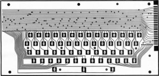
Now, there's some problems with this from a replicator's standpoint. One, there's only this one photograph of the unit. I've not found another picture taken of it, from another angle or anything. Since the unit's whereabouts are unknown, I can't ask someone for measurements as with the prototype. A lot will have to be inferred from the single photograph of the complete unit, and an extra, super grainy photo of the keyboard, which was its own project some months before:

RE_Feb_1973_pg55.jpg

As a railway modeller, I can handle all that. I'm used to working with next to no information and not being able to get real-world measurements. However the showstopper with this thing, until now, was the keytops. In the parts list from the 'low cost keyboards' article, a company called Mechanical Enterprises could be called upon to produce the keytops shown therein. I've searched on and off for 6 years without success in finding any. I assumed it was a lost cause and that's why I went to building the prototype, buying enough parts to do a couple of TVTs 'just in case'.

Anyway, one day last week I'm sitting around playing with my CT-1024 when I notice something. The keys on my terminal look just like the ones on the cover unit. I check and re-check a few times.. and sure enough.. it appears they are! Same concave keytops, square base, same height all around. The space bar, like the cover unit, is curved at the top. The one in the photo looks to be equal height on all sides, whereas mine is longer on the end facing the user. But I think that's just a trick of the photo. Given the relationship between SWTPC and RE at that time, it's not unreasonable to think they were getting their keys from the same places.

I also noticed on close inspection that the lettering on my SWTPC keyboard was painted on, not engraved. Reading the low cost keyboards article, Don made mention of being able to order the keytops with any 'reasonable callouts' on them. So there was a good likelihood that was why I couldn't find any keys like the ones on that unit: they were custom made for that project. And in fact, if you look at the photos, you can see one or two 'booboos' where the callouts/legends are not aligned properly with the others (ie the letters are too low). So, we're back to the realm of possibility here, since I have experience making rubber molds and being able to cast parts. What I realized I could do was 'borrow' the space bar and a few of the blank keys on my terminal and make a mold of them.

20151017_171113.jpg

Now, I don't have the skill to cast a part that complex exactly. What I'll end up with is a 'keytop' that is a solid block rather than a cap. But that's okay. The low cost keyboard design provides some flexibility. I can use a drill press and drill out the backside of the keys to a certain degree. Anyway, after the mold dried I did a couple of test castings:

20151018_085511.jpg

So, it's quite possible. I would have to paint the finished product, since it's not injection moulded plastic. But I think I can make it convincing. The lettering I'm guess will have to happen via silkscreen, and there's going to be some guesswork as to what some of the extra symbols were. But getting the actual keytops was really the worst of it. Now that I have a way to create those.. I can start thinking seriously about what materials I need to do the rest.
 
And here's the full set of keys reproduced (have to redo a few due to bubbles/deformities). I think it looks pretty bang on, despite colour.

20151018_151132.jpg
 
Another helpful thing with figuring out the dimensions of the cover unit -- the keyboard PCB itself. Here it is, printed out in full scale (gotta love large format printers!):

20151018_154209.jpg

I laid my keys on it just to check it out.. looks pretty good.

20151018_154747.jpg

Cool! And how appropriate as Halloween draws near I am slowly raising this thing from the dead!

This PCB is 14" by 6.75" according to the article. And if you look at the screw hole locations for the spacers, and compare to the cover photograph, we can confirm it lines up with all the screws seen in the photo, and can now can surmise that the width of the TV inside the plywood sides is simply the width of the keyboard -- 14". Cool! I can also use the height dimension to figure out the area under the keyboard. That leaves the height, which I can try to infer from any number of clues present in the photograph -- the screws, switches, etc. It'll be approximate only I guess, but, better than nothing. Wish there was a shot of the back!
 

Attachments

  • tvtkeyboard3.jpg
    tvtkeyboard3.jpg
    32.1 KB · Views: 2
It's a two part resin called Alumilite. The mold is made with silicone RTV, poured over original keys. The result is fairly high quality plastic. Negatives are that you have to paint afterwards, and the keycap is solid (I don't have the skills to do complex molds). But that isn't a problem for me since the low cost keyboard I'm recreating is a DIY project and I can come up with any number of ways to fit the keystem. I plan to drill out the backs with a drill press and then drill a smaller hole in the middle for keystems.
 
I'm so dumb -- spent a bunch of time squinting at photos of the cover unit's keyboard trying to figure out what symbols were on it, when low and behold they were right on the following page all along:

http://www.swtpc.com/mholley/RadioElectronics/Feb1973/RE_Feb_1973_pg57.jpg

So now we know that keyboard was modelled after an ASR-33. We also know that it was custom lettered. So the trick now is trying to get a font that is as close as possible to what was on the keys. And then figuring out a way to silkscreen it on there.
 
Another option for lettering is to take it to a locksmith or key cutter and have them engrave the caps. A small stand or jig for them to hold it might be needed. You then clean, paint, and use white crayon to fill the lettering, with the excess wiped or buffed off. At least that's what's sometimes done for vintage car dash knobs, I've done it myself and the results are good. However your keycap and paint would be a lot softer than a hard plastic or metal knob and may not take kindly to that last step, but you could experiment.
 
Would acrylic casting resin do just as well? You can get coloring agents for that stuff and the cure can be very hard.

Casting resin

I made my first digital LED clock with that stuff--embedded the LEDs in a black resin face.
 
Looking through some of the photos posted here of the original unit in the museum display (Back on pg. 2 of this topic) I cant help but think that the entire back/top of the case is a single piece of vinyl wrapped aluminum sheet.

It can be seen in the rear photo that the vinyl has shrunk slightly from the bottom edge revealing the aluminum, and the depth that the top switches are set at looks fairly shallow.
 
I kind of thought that too but came back to 3/4" plywood or MDF, based on one of the museum's photos of the top of the unit. In that photo, on the left side you can see the vinyl peeling away and there is a glimpse of what definitely looks like wood to me of some kind. Looking at the keyboard shop, the top appears to be about 3/4" thick. The plastic switch faces are mounted on a switch that stands almost an inch tall off the motherboard, so that works too. Further, the actual PCBs are mounted upside down to that top inside, but there are no protruding screws or evidence of anything popping up under the vinyl. Given how thin aluminum is, that would be very difficult to hide.

Looking through some of the photos posted here of the original unit in the museum display (Back on pg. 2 of this topic) I cant help but think that the entire back/top of the case is a single piece of vinyl wrapped aluminum sheet.

It can be seen in the rear photo that the vinyl has shrunk slightly from the bottom edge revealing the aluminum, and the depth that the top switches are set at looks fairly shallow.
 
I considered that but wasn't confident I could get the clean, glossy finish I needed to get on the colour. I'll check it out some more.

Would acrylic casting resin do just as well? You can get coloring agents for that stuff and the cure can be very hard.

Casting resin

I made my first digital LED clock with that stuff--embedded the LEDs in a black resin face.
 
Well, here they are. I can't believe it.. by all accounts, these shift registers are supposed to be impossible to find. 1976 date code is just a touch later than I wanted, but I'll take them.

20151030_161339.jpg
 
In between everything else, I've been learning about PCB etching and have gotten some boards I hope will give the correct-ish look to the project. They are supposedly 'natural' coloured FR4 boards, although right now with the copper on one side they look kind of brown from the back. Anyway, I've more or less mastered the laser transfer process (well, I guess we'll have to see how the etching turns out). I have a LaserJet 4250 printer with compatible toner -- basically I took the construction booklet photos Michael Holley was kind enough to post on his SWTPC website, enhanced them with Photoshop, and then resized using actual chips for scale. The TVT is four boards -- the mainboard, memory, timing and cursor. The latter three are small and I'm printing two to a board as I intend ultimately to make two TVTs.. one a replica of Don Lancaster's prototype, the other a replica of the cover unit. With photoshop I reverse the artwork, print it on pages cut from a Hotrod magazine, and then iron the pages to my copper clad for about 12 minutes. After that, dunk em in a big pot of cold water and pull off the paper after about 2 minutes. Here's the results:

20160618_120038.jpg

I did have it suggested to me by other more experienced retro-creators that I should just recreate the artwork in a CAD program and send to a fab house, get gold plate and all that jazz. While that would probably result in a more functional product, to me, it wouldn't be the same. There's something about using the original artwork (sort of) like they would have back in the day, and recreating it with some of the attendant imperfections that for me makes it more authentic. We'll see how I feel about that though after I get a taste of trying to make it work. :)

In terms of parts I have pretty much everything I need *except* the specific Signal '24-1a' transformer called for in the parts list. I did find one source but they want $400 per for NOS. Gasp! No luck on ebay yet either.
 
Yeah.. I have one of those actually.. but that's TVT II.. this is the original Lancaster one I'm working on.. I'm not sure how to make sure I have the right equivalent and more importantly right size since it has to mount in a tight space on the TVT mainboard.
 
Back
Top