• Please review our updated Terms and Rules here

Using PDPGUI to run BASIC

here is a video of my attempt to run CKBB. looking for a way to interpret this test.


https://www.youtube.com/watch?v=Lg_SLoKlMTs

page 14 of
http://bitsavers.trailing-edge.com/..._DCKBB-A_DCKBC-A_DCKBD-B_DCKBE-B_BASIC_CP.pdf

seems to indicate, my interpretation, that the program ran as expected, it loops and there is even a pass counter register. I don't see any error.


177776 = address of processor status word
177770 = address of ??? break register
etc.

how do interpret? When I halt, because it's looping it stops at various locations. When I look at the listing it seems to be NOT any of the error traps, it does NOT stop at places like:

001252 - error
001312 - error status word changed

I ran CQKC
same basic thing. The program runs. If I HALT the program stops at the point in the loop, but it's not or does not appear to be stuck. It's just doing its thing. Example stop locations/data:

005712 / 002
005774 / 000
005742 / 002
005746 / 004
005742 - 002
 
Last edited:
Test will run and ring the TTY bell (ie, sends a hex 0x07 character) at the end of each pass. Unless your terminal program is setup to respond to that character you likely won't see any response for each pass. Per doc's, location 1000 is a pass counter, so it should be incrementing.

These are real simple tests that exercise one instruction only (ie, SXT, SOB, XOR, ...) for each test. Useful only for very low level debugging of those instr errors.
 
right...so it was suggested I try these and I did. They appear to be running correctly as far as I can tell.

As stated my goal ultimately has been to attempt to load RT11 on an RL02. The M7762's that I have could be bad, the cables not right, terminator not working correctly, bad drive, bad media, etc. I have two drives. I can attempt various combinations of cards, drives, cables. I get similar results with a few combos, making me think there is a central issue. Taking a trip to Salisbury may be the next step, either me or mailing parts to be tested...??
 
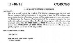
CQKCG0 is the most comprehensive test available for the 11/40, testing all CPU instructions and memory.

Per the diagnostic guide:
Capture.jpg

I would go for this prior to running the very detailed low level tests.
 
CQKC Test
Runs and HALTs at various spots, based on timing of when I depress halt, it's not jammed up.

005712 / 002
005774 / 000
005742 / 002
005746 / 004
005742 - 002
etc.

Reading the code of the program did not reveal too much as to a problem, but I am unsure if there are supposed to be switches set prior to running the program.
 
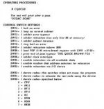
There are switches, of course:

Capture.jpg

Taken from the Diagnostic Handbook 1988 version on bitsavers.

You might want to start simpler, by disabling relocation (ie, don't use MMU). SW<9> and SW<7> both UP, all others DOWN.
 
I am trying to avoid the 1988 rev doc, seems way too new to be relevant to the 11/40, working instead from this, although it's the same thing:

http://bitsavers.trailing-edge.com/...D_D_1140_1145_INSTRUCTION_EXERCISER_Sep74.pdf

I don't have memory management installed, which is optional (section 1.1.2)

program loads into first 6K RAM. [ok]
Start address [200]
Because I am using a serial device, per the directions, deposit a 0 into location 1002 and 1003 enter 11 (octal), the counter.

SW10 up - ring bell on error.
SW7 - inhibit end of pass typeout (I don't want this)
SW9 - inhibit relocation.

I ran with 10 only, 10/7/9, just 7, etc.

I can see the program running, but nothing appears on the "teletype" screen.

I don't know if it's not printing to the screen because there is an error or if the M7856 is not what the program expects, or there is a setting that differs from what a teletype would have set, for some reason.

When I stop using the front panel, the program stops somewhere within 0057xx each time, this is not an error reporting section of code.
005712 / 002 -
005774 / 000
005742 / 002
005746 / 004
005742 - 002

BUT THEN....I found in chapter 6 that the execution time of the program is many (exactly now many don't know) minutes on an 11/40! It said 24 minutes to complete 8 passes with an 11/45, but no. I was assuming it was a lot faster. So I let it run with just switch 10 up (show end of pass to screen)

This might not be all, I may need to set more values in RAM after loading but before running to get my particular screen to output anything.

I will have to experiment with this wonderfully user-friendly program.

Looking at the code on page 44 - switches are described a little differently.

SW 15 = halt on error. I have run the program from 200 for 30 minutes with SW 15 up only.. still going. either it's ignoring the switch or there is no error.

page 45 has a list of the registers.

So...why do I feel like I am running around in circles looking for the earth below my feet? Also, is this only supposed to be run from a disk? Does plunking into memory work the same as running from the RT11 prompt?
 
Last edited:
Bill,

What are you doing with Switch 7?

You want SW7 OFF (i.e. don't inhibit end of pass message).

If SW7 is ON - you will get nothing on the console at the end of the pass and you have to infer it is working by not getting any halts or error printouts.

Diagnostics - by their nature need to be terse and wonderfully intuitive :)! If they require too much of the machine to be operational - then they will probably never work - as the reason for using the diagnostics is that the machine itself is suspect. Writing 'good' diagnostics is an art form - you have to start out assuming that everything is/could be faulty and have to 'prove' things are working from the ground upwards. For example, the PDP-8 diagnostics HALT when they detect an error (the HALT address being the key error indicator). But - how do we know that the HALT instruction actually works? The first diagnostic for the PDP-8 clears the accumulator and then HALTS. If it doesn't halt at the correct address with the ACCUMULATOR cleared - then this is an error! We now have a good 'feeling' that the HALT instruction works and we can use it to indicate subsequent errors.

Unfortunately, you need the exact same documentation that goes with the diagnostic you have. In PDP-8 land this was because the address of the HALT instruction indicated the problem.

The PDP-11 variant appears to be more complex than the earlier PDP-8 and you should setup the switches to display the textual messages associated with the error. The messages may seem terse to you - but believe me when I say they are better than a HALT address and trying to decode what went wrong.

As to time - good diagnostics take time. One of our memory diagnostics takes 98 hours to test 512 KBYTES of DRAM. We also have a simple memory diagnostic that takes a few minutes - but guess what - it misses subtle errors in the RAM card. We tested 150 odd memory cards a while ago - and only one was faulty. The 98 hour diagnostic found it - the simple one didn't... Go figure.

The diagnostic should print a message (and the pass number) at the end of the pass (if enabled). If not - this should be considered a diagnostic failure. Unfortunately, some faults will result in the diagnostics failing to report errors - been there seen that. The CPU ends up erroneously looping because of (say) a JUMP fault.

I am currently restoring an 11/45 that I recently acquired. It will take me some time to get the hardware cleaned up and restored - but I am using the time to locate all the diagnostics and documentation that I can. I will ensure that basic functions of the processor work by writing my own 'simple' programs entered from the front panel. I will also test out the console serial port with a test program of my own. Only then will I start with the diagnostics.

When I was helping Marty out with his PDP-8 build (and I was coding the PDP-8 in LOGISIM) - the PDP-8 diagnostics were invaluable as they identified a few things that didn't work. But we only started to run them when we were sure that the basic hardware did actually work as expected (i.e. the machine must be - say - 95% working to get the diagnostics to work. The diagnostics then found a few things that didn't work).

I agree with swapping boards around to get the system basically to work - but then you have to run the basic diagnostics to give you confidence that the machine is actually working. Even then - you can't be 100% sure...

Don't be disheartened and keep at it. Read the documentation associated with the specific diagnostic and (if it is unclear) ask here and we will help out. The PDP-8 diagnostics were pretty accurate with their estimate of how long they would take - as there were fewer processor options. I agree that the description is (at best) confusing with the PDP-11 one you have identified. Most diagnostics start at low memory and work their way up memory as tests pass (especially if you switch off the relocation feature). I used this fact on the PDP-8 to follow the diagnostic progress. Again - you need a listing to follow.

Also - keep a notebook of everything you try. I started a notebook the day I picked up my 11/45. Every time I do something I note it down in the notebook. In your case, this would include how I loaded something, what the switch settings were and what I observed. As you point out - time seems to be a critical factor; so the time of starting a test and when you stopped it would be something to note down. Machine configuration when you are doing a test (e.g. cards installed, memory etc.). This all may sound like a ball ache - but in a few days or weeks you will want to know what you did and (if you haven't noted it down) you won't be able to remember. Also, when we ask questions like "was SW7 ON or OFF" and "how long did you wait since starting the diagnostic with SW7 OFF" you will be able to give us the answers.

I am not against trying to load RT11 and BASIC - if it works all well and good. But if it doesn't work - this configuration won't tell you anything (hence the reason for the DEC diagnostics in the first place). If you can't get the DEC diagnostics to work (barring not running them correctly of course) I wouldn't expect RT11 or BASIC to work (except by a fluke).

It would appear that most of the 11/40 and 11/45 diagnostics are common - so I will benefit directly from helping out here if I can. Can you provide links to the diagnostic tapes and documentation you are using and I will have a read myself and suggest a few things? If we are using the same things - we have a common frame-of-reference. It might take me a few days to catch up with reading this thread though.

Dave
 
Last edited:
When I stop using the front panel, the program stops somewhere within 0057xx each time, this is not an error reporting section of code.
005712 / 002 -
005774 / 000
005742 / 002
005746 / 004
005742 - 002

Have you tried single stepping the machine and compare the flow against the listing? It can be all sorts of problems that causes it to not come out of a loop.
 
As someone who worked at DEC in the PDP-11 diagnostics group from 1975 thru 1979 writing diagnostics for the PDP-11/60 in particular you need to be aware of some of the requirements of the time.

All the communication of program running options was to be done thru the 16 bit hardware switch register, or if need be extra memory locations that the operator could be set to values by the operator. Any kind of long question/answer query dialogs to the operator via console was not permitted.

Diagnostics were required to be able to be run in the minimum memory configuration supported, which at the time was 4KW. So each diagnostic image had to be able to load and run in 8192 bytes of memory. After accounting for all the necessary test code, not a lot of space left over in 8KB to put a lot of very verbose error messages for each test failure. Usual was to dump out some registers, possibly some expected/received memory locations, and then halt. Operator was then to look in the printed diagnostic listing for further info. The console printout alone was not intended to be sufficient to diagnose the problem.

And the diagnostics were intended to be at most targeted for field service techs doing board swap repair. They were not intended to provide resolution to specific chip failures. Failed boards would be swapped out and sent to DEC depot repair facilities where chip level debug would be done using other capabilities (DEC was big into module level XOR testers at the time in its manufacturing test process).

To my knowledge the only chip level repair diagnostic facility provided for a specific PDP-11 system was the PDP-11/60 DCS (Diagnostic Control Store) module I implemented for the 11/60 processor. This was 4K of custom microcode that replaced the normal CPU microcode and ran tests and provided info to narrow down failures to the chip level (using a printed fault dictionary). The fault dictionary was built by running an entire CPU thru chip by chip fault insertion, and recording the failure code for each fault on every IC pin in the CPU board set. As I recall we built an 11/60 with all chips in sockets, and then a tech pulled chips one by one, inserted a test head that could do stuck-H/stuck-L/adjacent-short in each site (along with the pulled chip) and then ran the microdiagnostic with the inserted fault. Failure code (or not :-( ) was recorded. Anyway this was a separate plug in module that field service could carry to 11/60 sites to do field repair. It was not just a runnable s/w image.

So when you are working on your 11/20, 11/05, 11/40, 11/45, 11/04, 11/34, 11/60 think about these restrictions that were imposed on the diagnostic writer at the time.

Don
 
Last edited:
Hi All;

Dave, Thanks for the Idea of the Complete notebook..
I have used as You know Notebooks for Schematics and hints on programs for the PDP 8i clone, but not so much for Everything else..
So, Yes, I would agree with You, Keep track of Everything and like I am thinking now, I couldn't tell You How to Run, How to Load either of my machines from what is in my memory..
I will need to start all over on either one.. So, Yes Thank You, Dave !!

THANK YOU Marty
 
I always keep a spiral notebook...that was the birth of vintagecomputer.net, simply a site with my notes on it. You can always get more details from posts here, there. I totally get why things are the way they are with the diagnostics, but I can still complain.

I am expecting to see output, terse as it might be, to the screen as described in the code. I am not yet seeing anything. That needs to be resolved by understanding what I am not doing right here.

I have experimented with various switches- and what I mean by that is raising a switch up before running a given diagnostic.

bill
 
Last edited:
Dave - I was told to start with 9 and 7 SW on, but later I said I disagreed with this. There is a lot in this thread, you'd have to read it all to get all of the details.

At present I am working with...
http://bitsavers.trailing-edge.com/...D_D_1140_1145_INSTRUCTION_EXERCISER_Sep74.pdf

...and in particular CQKC. chapter 6 is useful.

How do I interpret page 21 of the doc referenced above? based on the chart of switch settings on page 7 I have tried SW 15 / 3 /2 /1 /0
results - nothing to display, but does not bomb out.

tried also only switch 15 up. - no difference. program runs but does not bomb, but nothing to screen.

It seems to me that one should get something to the screen at the end.


b
 
Last edited:
Dave - I was told to start with 9 and 7 SW on, but later I said I disagreed with this. There is a lot in this thread, you'd have to read it all to get all of the details.

Since you don't have the MMU option installed you must run with the MMU test option disabled, or else you will get a failure.

At present I am working with...
http://bitsavers.trailing-edge.com/...D_D_1140_1145_INSTRUCTION_EXERCISER_Sep74.pdf

...and in particular CQKC. chapter 6 is useful.

How do I interpret page 21 of the doc referenced above? based on the chart of switch settings on page 7 I have tried SW 15 / 3 /2 /1 /0
results - nothing to display, but does not bomb out.

The info on page 21 shows a memory word that is filled in with the detected system characteristics. Memory word OPT.CP location 000764 is that location (at least in the version of diagnostics that the listing is for). That table of bits is NOT to be inferred as how the switches should be set.

tried also only switch 15 up. - no difference. program runs but does not bomb, but nothing to screen.

It seems to me that one should get something to the screen when you first start the program.

b

Some CPU failures can result in an infinite test loop where no progress is made but the CPU keeps on running.

There is not usually a 'hello' message in the early diagnostics. Basically they would start running with no indication, and just ring the TTY bell at end of pass. Maybe nothing printed out at all unless an error message is produced. Some diagnostics will print a successful end of pass message with a pass count, this was done starting in the 11/34 generation or so. 11/40 and 11/45 were basically first generation diagnostics so were very spartan with respect to user interaction.
 
I get it, terse output but I read the code and found what prints when the tops. At the end of each pass it's supposed to say:

THE QUICK BROWN fOX JUMPED OVER THE LAVY DOGS BACK
0123456789
PASS # AAAA

I am going to run this for an hour to see if ANYTHING prints, especially this end of pass message. The doc says an 11/45 with a lot of RAM will complete a pass in 24 minutes. What my 11/40 with 16K will need I don't know, but I can't imagine more than 40 minutes.

If console TTY is a serial device filler characters are required. Deposit into location 1002 a 0 (the filler character) and location 1003 11 octal the filler count.

start address 200
press start
set operating switches

contents of OPT, CP is typed on first pass.
Pass count is printed after each pass
DCQKC DONE is printed when done.

7 = means don't type out the pass typeout - I assume I should leave this switch down.
15 = halt on error - this is the only switch in the up position.

the lights flicker.
 
Last edited:
According to the DEC Diagnostic Handbook you need SW<07> to be UP ('1') to enable the 'QUICK BROWN FOX ...' printout at end of each pass. Otherwise with SM<07> down you will just get a terminal BELL at end of pass.
 
ok, it's up now...I further assume one can raise a switch while the program is running and it will "take effect" for the next pass?
 
ok, it's up now...I further assume one can raise a switch while the program is running and it will "take effect" for the next pass?

It depends on how the diagnostic was written. Usually yes, but not guaranteed. Would have to look at the code listing to be certain.
 
Back
Top