Thanks.
So we are talking about very small voltages - and very small currents.
I think what you are observing as signals on Q505 collector and emitter are as a result of the Z-axis attempting to switch on Q505.
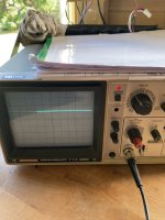
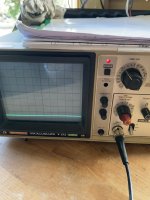
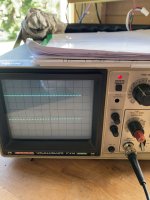
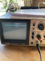
Looking at Q505 emitter you say that the voltage switches between 0V and +0.18V. I suspect this to be as a result of the base current flowing from the Z-AXIS signal, through R513 into Q505 base. The current then flows through the emitter resistor (R515) and a voltage difference is generated across R515. Dividing 0.18 Volts by 150 Ohms gives me 1.2 mA of current.
The signal on Q505 collector is a 'strange amplification' of the Q505 base/emitter current - but with a very limited voltage source.
I suspect that Q503 is switched OFF and this is leading to all of our problems.
The circuit in the base of Q503 works as follows:
The Y-DRIVE signal is monitored via R417 and C409. C409 acting to block any DC component of the Y-DRIVE signal - thus permitting the actual deflection voltage change through. D402 shunts any negative voltage pulses to 0V/GND. D401 passes positive pulses through to charge up C410. R530 acts to discharge C410 when no input pulses are present.
Under normal circumstances, positive deltas of the Y-DRIVE will charge C410 and it should stay charged as long as there is Y movement (in one direction). The voltage that has built up on C410 is limited to 6.2 Volts by the series resistor R503 and zener diode DZ501. The resulting voltage is passed via R510 to the base of Q503 - thus turning it on.
Basically, when Y-DRIVE signals are present, Q503 should be turned ON. When Y-DRIVE signals cease, Q503 turns OFF.
When Q503 turns OFF, the CRT cathode gets pulled up to +50V via R512, and transistors Q401 and Q402 are turned OFF via Q504.
Now I have a problem - because I have a 'chicken and egg' situation. If I have turned off Q401 and Q402 - I have seriously reduced the X and Y drive signals to IC401. This, in turn, limits the Y-DRIVE signal that I am monitoring in order to turn Q503 ON (and hence turn Q401 and Q402 ON).
I am not sure how this circuit is now supposed to work - I am missing something here...
We could try an experiment to see if we can stimulate the base circuit of Q503 to operate, so we can see whether that 'fixes' the problem or not. If not, it may give us some additional information in order to help us diagnose the fault further.
What I am thinking of is to temporarily connect a resistor to supply some volts to the monitoring circuit to cause Q503 to switch ON. We might need to do this via a pushbutton to ensure that if anything else is wrong, we don't damage the CRT by burning a spot on it. Let me think about this a bit more, and let me have a think and a read about how this circuit SHOULD work correctly.
Dave


