I agree, there is something amiss here somewhere...
Let me describe how I think the Z circuit should work...
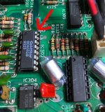
That DAC is setup to output a voltage from IC304/1 into the multiplexer IC IC302/13 (IN1). From my understanding, this should be fully positive for 'beam on' and fully negative (?) or 0.0V (?) for 'beam off'.
SEL1 should be set to '1' and SEL0 should be set to '0' with DIS '0' to enable IN1 to OUT1C. In this mode, the input signal from the DAC should be output to the Z channel on IC302 pin 15.
C306 is the sample and hold capacitor. The capacitor is charged up to the analogue voltage that is output on OUT1C.
IC303 (on the Z channel) is a very high input impedance voltage buffer. The output voltage on pin 8 should always be the same as the input voltage on pin 10.
When IC302 pin 6 (DIS) is set HIGH, the output at OUT1C should become open circuit and the voltage that was originally stored on C306 should remain (due to the high input impedance of the following IC303 OPAMP).
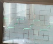
Now look at the output of IC303 at pin 8.
If the /BLANK signal goes LOW - this causes the Z signal to go low and blank the beam.
If the /BLANK signal is HIGH - this is the pull-up voltage to turn the beam ON.
However, if the output from IC303 pin 8 goes negative, this drags the Z signal down (via diode D302) and this also blanks the beam.
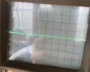
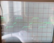
My expectation is that the Z signal is either ON or OFF (as per the manual) and not as you are observing it.
The question now remains as to why it is like it is. If we can answer this, it may 'open up' the other faults.
Dave
")