- VCF South West - June 14 - 16, Davidson-Gundy Alumni Center at University of Texas at Dallas
- VCF West - Aug 2 - 3, Computer History Museum, Mountain View, CA
- VCF Midwest - Sept 7 - 8 2024, Schaumburg, IL
- VCF SoCal - Mid February 2025, Location TBD, Southern CA
- VCF East - April 2025, Infoage Museum, Wall NJ
-
Please review our updated Terms and Rules here
You are using an out of date browser. It may not display this or other websites correctly.
You should upgrade or use an alternative browser.
You should upgrade or use an alternative browser.
VECTREX WITH DESPERATION
- Thread starter Desperado
- Start date
daver2
10k Member
I am afraid that doesn't help me...
Dave
Dave
Desperado
Veteran Member
- Joined
- Nov 25, 2017
- Messages
- 6,827
I have this boardI am afraid that doesn't help me...
Dave
Attachments
I am desperate, where i losted this -13V????
Goodness, what kind of life-saving medical equipment is this Vectrex going to be used in?
Desperado
Veteran Member
- Joined
- Nov 25, 2017
- Messages
- 6,827
Hi, i have only a diagnostic cart, logic probe and oscilloscope...Goodness, what kind of life-saving medical equipment is this Vectrex going to be used in?
daver2
10k Member
That is more helpful.
The -13V is derived from a lower AC voltage obtained from the transformer secondary winding - and then doubled via a diode/capacitor network.
At this point I am not concerned with why you don't have a -13V supply, but why is the AC input supply from the transformer to the voltage doubler not working as expected?
I will post a snipet of the schematic tomorrow and we will take it from there.
Dave
daver2
10k Member
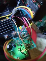
Can you see the mains transformer?
There should be one white wire and two red wires coming out of the transformer secondary windings.
The two red wires should go to (and from) a switch. Then via a torroid (ring) ferrite core, and then the red and white wires should be attached to the power board.
Can you follow these wires?
Dave
There should be one white wire and two red wires coming out of the transformer secondary windings.
The two red wires should go to (and from) a switch. Then via a torroid (ring) ferrite core, and then the red and white wires should be attached to the power board.
Can you follow these wires?
Dave
daver2
10k Member
I am going to sleep also!
Dave
Dave
daver2
10k Member
The transformer windings are used to produce the + and - 5V rails - and these appeared good...
My 'plan' would be for you to measure the AC voltage between the WHITE wire and the two RED wires (2 measurements) and then between the two RED wires. If you could measure these voltages with your multimeter probes both way round and where the wires attach to the power PCB.
If this makes sense?
Make sure you mark the two RED wires in some way to differentiate them from each other") .
.
Dave
My 'plan' would be for you to measure the AC voltage between the WHITE wire and the two RED wires (2 measurements) and then between the two RED wires. If you could measure these voltages with your multimeter probes both way round and where the wires attach to the power PCB.
Code:
WHITE and RED1 - probes BLACK=WHITE and RED=RED1.
WHITE and RED1 - probes BLACK=RED1 and RED=WHITE.

WHITE and RED2 - probes BLACK=WHITE and RED=RED2.
WHITE and RED2 - probes BLACK=RED2 and RED=WHITE.

RED1 and RED2 - probes BLACK=RED1 and RED=RED2.
RED1 and RED2 - probes BLACK=RED2 and RED=RED1.
If this makes sense?
Make sure you mark the two RED wires in some way to differentiate them from each other
.Dave
Desperado
Veteran Member
- Joined
- Nov 25, 2017
- Messages
- 6,827
Ok thanks but must i measure these voltage directly on power board?The transformer windings are used to produce the + and - 5V rails - and these appeared good...
My 'plan' would be for you to measure the AC voltage between the WHITE wire and the two RED wires (2 measurements) and then between the two RED wires. If you could measure these voltages with your multimeter probes both way round and where the wires attach to the power PCB.
Code:WHITE and RED1 - probes BLACK=WHITE and RED=RED1. WHITE and RED1 - probes BLACK=RED1 and RED=WHITE. WHITE and RED2 - probes BLACK=WHITE and RED=RED2. WHITE and RED2 - probes BLACK=RED2 and RED=WHITE. RED1 and RED2 - probes BLACK=RED1 and RED=RED2. RED1 and RED2 - probes BLACK=RED2 and RED=RED1.
If this makes sense?
Make sure you mark the two RED wires in some way to differentiate them from each other
Dave
daver2
10k Member
You can measure them at either end of the piece of wire... It shouldn't make much difference (unless we have a broken wire)...
Dave
Dave
daver2
10k Member
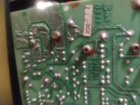
They look right (if they come from the transformer via the switch).
The white lead should be marked EP105 on the PCB and the two (2) red leads should be marked EP104 and EP106 on the PCB.
Dave
The white lead should be marked EP105 on the PCB and the two (2) red leads should be marked EP104 and EP106 on the PCB.
Dave
Desperado
Veteran Member
- Joined
- Nov 25, 2017
- Messages
- 6,827
10,2 VACWHITE and RED1 - probes BLACK=WHITE and RED=RED1.
10,2 VACWHITE and RED1 - probes BLACK=RED1 and RED=WHITE.
0,27 VACWHITE and RED2 - probes BLACK=WHITE and RED=RED2.
0,27 VACWHITE and RED2 - probes BLACK=RED2 and RED=WHITE.
10,2 VACRED1 and RED2 - probes BLACK=RED1 and RED=RED2.
10,1 VACRED1 and RED2 - probes BLACK=RED2 and RED=RED1.
daver2
10k Member
Not just yet...
I find an inconsistency in the WHITE and RED2 readings...
Question: Is the RED2 wire connected to the pad marked EP104 or EP106?
I think I can guess - but I want you to confirm...
Dave
I find an inconsistency in the WHITE and RED2 readings...
Question: Is the RED2 wire connected to the pad marked EP104 or EP106?
I think I can guess - but I want you to confirm...
Dave
Desperado
Veteran Member
- Joined
- Nov 25, 2017
- Messages
- 6,827
EP106Not just yet...
I find an inconsistency in the WHITE and RED2 readings...
Question: Is the RED2 wire connected to the pad marked EP104 or EP106?
I think I can guess - but I want you to confirm...
Dave