• Please review our updated Terms and Rules here

VECTREX WITH DESPERATION

I noticed that it depends on the tip of the multimeter... sometimes it doesn't score and sometimes it does... :(
 
So, now measure from the WHITE wire to the + side of the PCB where C120 was originally fitted (multimeter set to AC volts still).

Dave
 
I noticed that it depends on the tip of the multimeter... sometimes it doesn't score and sometimes it does... :(
This is why I asked you to clean up the solder joints.

If you also do not get the correct voltage - you need to try, try and try again just to make sure...

Dave
 
Excellent. Now we are cooking with gas...

Solder back C120 into circuit - making sure that you put it in the right way round.

Check for -13V DC (don't forget to change your multimeter to DC volts) relative to 0V/GND at either P201 (or IC301 pin 3) whatever is easiest.

Dave
 
Dave ,good morning!
I solded new C120 and i turned on the Vectrex!
I don't know why but now i have a screen! it's all shaking but now i can see something!
Maybe bad capacitors??
 
I read troubleshooting manual for this synthom and i see this:
 

Attachments

  • Screenshot 2023-04-06 alle 12.40.03.png
    Screenshot 2023-04-06 alle 12.40.03.png
    183.3 KB · Views: 4
I suspect that you had a bit of a faulty switch (SW301). This switch works on both secondary windings of the transformer. With one side of the switch working, and the other not, you will get the observed symptom (no -13V rail) and the DAC will not work correctly.

Yes, now I suspect you have some capacitor problems - either in the power supply (high probability) or in the DAC / sample and hold or integrator parts of the logic board. Possible even the monitor electronics.

Glad to see you read the troubleshooting manual! That is what it is there for.

We have already taught you how to use your oscilloscope for this on the last PET. But here it is spelled out for you in the troubleshooting manual.

Glad we didn't wave the white flag in the end...

Dave
So what what do you suggest to do as a first step? change the capacitors indicated in the manual?
 
I suspect that you had a bit of a faulty switch (SW301). This switch works on both secondary windings of the transformer. With one side of the switch working, and the other not, you will get the observed symptom (no -13V rail) and the DAC will not work correctly.
If it were possible to open the switch, could I spray contact spray inside?
 
So what what do you suggest to do as a first step? change the capacitors indicated in the manual?
No,

Perform the identified tests with your oscilloscope to identify IF there is a problem FIRST - and then (if a problem is identified with a particular voltage rail) we can perform further tests to narrow the fault down to an individual component (be that a capacitor, diode etc.).

Use test equipment and brain first (not necessarily in that order) and then replace the minimum number of components. That way it keeps the 'original vintage' nature of the machine and protects the PCB from any resultant damage due to exchanging non faulty components.

Otherwise, your approach to replacing a load of components is what is termed a "scatter gun" approach.

Post the results of your oscilloscope tests and we can take it from there.

Dave
 
If it were possible to open the switch, could I spray contact spray inside?
My gut feeling is to spray a bit of PROPER contact cleaner onto the switch and operate it a few times. Hopefully the cleaner will penetrate into the switch unit and clean/lubricate the switch contacts.

Dave
 
I am desperate because now i have again only dot on the screen :( why?
 
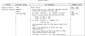
ok but i can't understand this " CHECK RIPPLE AT T503 ".....

1. Find component T503 on the schematic and the PCB layout.
2. Notice on the schematic that T503 has two supply inputs (marked as +IN and -IN).
3. Stick your oscilloscope probe on each of these points in turn.
4. Measure the voltage rail ripple.

Simple as...

Dave
 
I am desperate because now i have again only dot on the screen :( why?
Check the -13V rail again then...

It may be something else of course...

This looks to be a 'none permanent' issue - so is probably a faulty switch, connector, solder joint etc. Unlikely to be a component. Use your eyes, magnifying glass and bright light. We have been here before haven't we... Spend quality time looking at the boards etc.

Dave
 
In terms of voltages - you should read the following:

AC Voltage range:

Approximately 10V AC between points EP104 and EP105 on the power board.

Approximately 10V AC between points EP105 and EP106 on the power board.

DC Voltage range:

Approximately +9V across capacitors C117 and C118.

Approximately -9V across capacitors C109 and C119.

+5V across capacitor C111.

-5V across capacitor C110.

Approximately -13V across capacitor C122.

You may find it easier to solder some temporary wires onto the voltage rails and 0V/GND and bring these out to a screw connector block for ease of measuring. Especially if the fault is intermittent. You can then assemble the Vectrex boards back into the case (for your safety) and the power rails are easily available on the connector block for probing should this be necessary.

Measure the DC rails on a DC setting of your oscilloscope to start with - to ensure the average DC Voltage level is within specification. Then switch the oscilloscope to the AC setting and increase the Y sensitivity knob (V/div) to see any noise/ripple that should be present. Check that the noise and ripple (noise being high frequency and ripple being mains/low frequency) is also within specification. Remember from the PET work that there is ALWAYS noise present - the issue is "how much" (so I don't want to see any statements like there isn't any noise!).

Dave
 
you're right Dave, it's the switch that sometimes works and sometimes it doesn't.... I measured directly on the wires that go to the switch and in a red wire the 10 VAC is still not coming out. It seems that it can be disassembled ... I have to try to remove it and check
 
you're right Dave, it's the switch that sometimes works and sometimes it doesn't.... I measured directly on the wires that go to the switch and in a red wire the 10 VAC is still not coming out. It seems that it can be disassembled ... I have to try to remove it and check
Good investigation.

See, no need to be desperate...

Dave
 
Back
Top