• Please review our updated Terms and Rules here

What did I do to my PDP-8 today.

IMG_0287.JPG
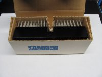
This is a New In Box H800W. I have two of these. The other one I turned into a card extender years ago because I didn't have a dual width extender.
IMG_0286.JPG
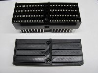
The top one is the H800W out of the box. Note that these are single sided. They were in a box of stuff I got with my Straight 8. Probably ordered to build a custom interface and then never used. The Rapid City flood in 1973 changed the way the machine was used. They never hauled it to the Radar Site after the flood. It was used only for the Minicomputers class. The bottom is the start of a 3D model I made from it. My goal is not to make a usable backplane, but for card storage. This fits single and double wide cards very well.
IMG_0284.JPG
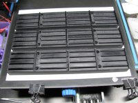
These are close to what I am actually going to use. The one closest to the bottom is dimensionally accurate to an actual omnibus. Which means it won't work all that well for storage as the cards are not easy to get in and out without rocking. The middle one has chamfers on the slots and minor changes to the geometry. The top one is very close to what I am going to use. I increased the chamfers more because my M837 card hangs up in the slots. There are feed thru holes filled with solder adjacent to the gold edge connector fingers. The solder just catches in the slot. I found that it still hangs a little with the top one so I am printing a 4th with even larger chamfers. These are printed in draft mode and take about 4 hours each. The first one has 3 bottom layers and 4 top layers and looks better. The others have 2 bottom layers and 2 top layers. There is about a dollars worth of plastic in each one. I used the bed of my old CR-10 3D printer with a sheet of paper on it as a photo platform. It has good light over it. The printer originally cost about $400 but I have done a lot of upgrades and while it prints a lot better I would have been better off spending more up front.

I was originally going to use bankers boxes with these mounted in the bottom somehow. I stopped at an office store and looked at them and found that there are plastic ones instead of cardboard. The plastic ones are waterproof and would provide better protection so I am probably going to do that. I currently have 44 quad omnibus boards and maybe 20 hex width. But some of these will be in machines so will not need to be stored.
IMG_0289.JPG
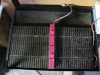
This is the omnibus from the DECset 8000 (8/e) just before cleaning. I noticed that the M935 connectors don't fit quite right. Are M935 the correct ones for an Omnibus? They seem to be high centered and can be rocked back and forth so as to be inserted at an angle. This just doesn't seem correct. This need a close look. Also the handle designation is upside down on one of them. I was originally concerned that one of them was in backwards but that is not the case.
 
Last edited:
The M935 connectors mentioned in the previous posting rock in the connectors. I verified with Vince that his will do this as well. It has to do with how the backplane was designed, not something specific to this machine. In other words, all of them will do this. I don't know if you can tip them enough to cause a problem.

In the bottom photo of the previous posting the left 20 slot backplane and the right one are different shades of black. I think they are not originally from the same machine. The question then is was this the good machine or the one where they put the broken bits. The left backplane has chipped bakelite in the alignment ridges. This sometimes happened when a card got jammed and a screwdriver was used as a prybar. I removed both to give them a good cleaning and to ensure that there is no loose hardware underneath. The solder joints on the left one are more corroded than the one on the right. There was also some oily residue on the bottom, perhaps overzealous use of contact cleaner/lubricant? On the other hand, the right one had an edge connector finger in slot 38 or 39 connector C pin S that was bent funny and appeared to connect from side 1 to side 2. I inserted a card in just the connector and removed it and this looks like it put everything back in place. The signals that were potentially shorted together are SKIP L and LINK LOAD L. I doubt the machine would have worked very well if those were shorted.

There was nothing conductive beneath the backplanes. However there were wood chips embedded in the pins. At some point the left backplane had been placed on a not too clean workbench.

I ordered another 2 kilos of plastic so I can go into production of storage connectors. I appear to have 44 quad width omnibus cards although some of those will be stored in machines.
 
Which reminds me - I am looking for one or two power cables from the H724 PSU to my two OMNIBUS backplane sections for my PDP-8/E if anyone has a small surplus and you want to sell the odd one or two?

Dave
 
Which reminds me - I am looking for one or two power cables from the H724 PSU to my two OMNIBUS backplane sections for my PDP-8/E if anyone has a small surplus and you want to sell the odd one or two?
These would be easily fabricated from new parts. DigiKey carries exact housings and pins for the H724 side and probably the other side as well although I can get the spade lug style stuff at any auto parts store. If you want to go all out you can even get the pins in a gold plated version. The correct crimpers would be nice.

I just noticed that the front and rear cables are different lengths with no reason that I can see. The rear one was the longer one. Since I swapped the backplanes now it is on the front. I will switch them if I can come up with a reason to. Of course the different lengths might be because the cable assemblies came from different production runs.
 
Which reminds me - I am looking for one or two power cables from the H724 PSU to my two OMNIBUS backplane sections for my PDP-8/E if anyone has a small surplus and you want to sell the odd one or two?

I just went through this last week at LSSM, as we were missing one harness and one of the H744-side connectors was damaged and needed replacement. The connectors are available; I bought them from Mouser. In case you end up having to make one, here's the info from my notes:

Power supply side (H744)
------------------------
Shell TE Connectivity 1-171196-0
Pins TE Connectivity 60619-1

Cable to backplane side
-----------------------
Shell TE Connectivity 1-480276-0
Pins TE Connectivity 60620-1

-Dave
 
Worked on the OS/8 serial disk over the console port handler today. Here is what I have so far. Completely untested of course since it can't be tested without a completely rewritten server.


Code:
/ SERIAL DISK OVER THE CONSOLE PORT
/
/ 20220213 DPI
/       STARTED CODING SINGLE SYS ENTRY POINT.

/ 20220218 DPI
/       FLESHED IT ALL OUT.  JUST EXACTLY FITS WITHOUT ANY TRICKS.

        VERS="A&77      /VERSION DISPLAYED BY RESORC

        DEVCNT=1        /JUST THE SYS ENTRY FOR NOW
        DECIMAL
        DEVSIZ=3248     /SAME AS RK05 AND PREVIOUS VERSIONS FOR NOW
        OCTAL


        *0
        -DEVCNT         /NUMBER OF ENTRIES

        DEVICE SDCO; DEVICE SYS; 4400; 2007; 0; DEVSIZ


/BOOT CODE ISN'T USED BY SERIAL DISK BOOT ANYWAY.

/////// START OF UNUSED BOOT.  BUILD NEEDS SOMETHING.
/////// MAKE THIS ZEROS AT SOME POINT?  CAN BE UP TO 43 OCTAL WORDS

        BOOT-BLAST       /TWO'S COMPLEMENT OF LENGTH OF BOOT CODE FOR BUILD

        RELOC 0

BOOT,   NOP             /NO BOOT CODE HERE.  THE SERVER HANDLES IT.
BLAST,  RELOC

        NOPUNC
        *0026           /PLACE HOLDER FOR READ ADDRESS
/THIS IS THE BOOT 1 CODE THAT GETS OVERWRITTEN
        NOP             /FOR NOW
        ENPUNC

/////// END OF BOOT


/ THE HANDLER STARTS HERE

        *200
        RELOC 7600

        ZBLOCK 7        /SKIP OVER THE OS/8 RESTART CODE

SYS,    VERS            /RESORC DISPLAYS THIS AS THE VERSION NUMBER
        CLA CMA CLL     /GET AC AND LINK TO A KNOWN STATE
                        /-1 IN THIS CASE TO INIT TSFSET

/SD SHARES THE CONSOLE PORT.  THE CALLER COULD HAVE JUST SENT A CHAR SO
/ WE WAIT UP TO A CHAR TIME OR UNTIL THE FLAG IS SET.
        DCA TSFSET      /INITIALIZE THE TSFSET FLAG TO INDICATE NOT SET
        TAD BDTIME      /WE NEED TO WAIT A CHARACTER TIME
        DCA TEMP        /INITIALIZE THE TIMER COUNTER
BDLP,   TSF             /GET STATE OF TRANSMIT FLAG
        JMP NOTSET      /WE WAIT FOR ONE
        ISZ TSFSET      /MARK TSF FLAG AS SET
        JMP WAKEUP      /WE GOT NO TSF FLAG.  SEND SERVER WAKEUP

NOTSET, ISZ TEMP        /HAVE WE WAITED A CHARACTER TIME?
        JMP BDLP        /NOT YET

/WE NEED TO WAKEUP THE SERVER.  WE SEND IT THE WAKEUP CODE OF 02X WHERE
/THE X IS REPLAED BY THE CALLERS DATA FIELD.

WAKEUP, RDF             /GET THE CALLERS DATA FIELD IN 6-8
        RTR             /SHIFT RIGHT 3 BITS
        RAR
        TAD WKUP        /ADD IN THE WAKEUP CODE
        TLS             /SEND THE WAKEUP COMMAND TO THE SERVER

/ NOW SEND THE ADDRESS OF THE CALLERS ARGUMENTS
        TAD SYS         /GET POINTER TO ARGUMENTS
        JMS SEND12      / AND SEND IT


/AT THIS POINT THE SERVER IS IN DISK MODE AND WON'T SEND ANYMORE
/CHARACTERS FROM THE KEYBOARD.

/NOW HANDLE THE KEYBOARD
        CLA CMA         /A -1 MEANS NO CHARACTER WAS WAITING TO BE READ
        KSF             /IS THERE A CHARACTER
        SKP             /NO CHARACTER SO SKIP THE READ
        KRB             /READ THE CHARACTER AND CLEAR THE FLAG
        DCA KSFSET      /REMEMBER THIS
        TAD KSFSET      /AND SEND TO THE SERVER
        JMS SEND12

/NOW WE GO INTO COMMAND MODE AND DO WHAT THE SERVER TELLS US.

CMDLP,  JMS GET12       /READ THE ADDRESS
        DCA BUFFER
        JMS GET12       /READ THE WORD COUNT
        DCA COUNT
        JMS GET12       /READ THE COMMAND
        SMA             /TEST FOR JMP COMMAND
        JMP RDORWR      /IT IS A READ OR A WRITE COMMAND
/WE HAVE A JMP COMMAND.
/ FIX UP THE TSF FLAG IF NECESSARY
        ISZ TSFSET      /SKIP IF TSF FLAG WAS SET ON ENTRY
        TCF             /ELSE CLEAR IT

/HANDLE KSF AND CHARACTER IN INPUT BUFFER.  IF NECESSARY THE SERVER WILL
/RESEND THE CHARACTER.
        ISZ KSFSET      /SKIP IF WE NEED TO WAIT FOR CHARACTER
        JMP DOJUMP      /FLAG WAS NOT SET ON ENTRY
        KSF             /WAIT FOR SERVER
        JMP .-1

DOJUMP, DCA .+1         /COMMAND IS THE CDF CIF TO THE JMP FIELD
        HLT             /OVERWRITTEN BY A CDF CIF TO THE DESTINATION FLD
        TAD COUNT       /COUNT IS VALUE LOADED IN THE AC
        JMP I BUFFER    /AND PERFORM THE FAR JMP

RDORWR, RTL             /LINK CLEAR IF READ, SET IF WRITE.
        TAD CDFINS      /BUILD THE CDF INSTRUCTION
        DCA .+1         /AND EXECUTE NOW
        HLT             /THIS BECOMES A CDF TO THE USERS BUFFER
        SZL             /IS THIS A READ
        JMP WRCMD       /NO IT IS A WRITE

RDCMD,  JMS GET12       /GET READ BYTE FROM SERVER
        DCA I BUFFER    /STORE IN USERS BUFFER
        ISZ BUFFER      /POINT AT NEXT
        NOP             /IN CASE IT WRAPS AROUND
        ISZ COUNT       /ARE WE DONE YET?
        JMP RDCMD       /NOT YET

        JMP CMDLP       /GO GET NEXT COMMAND

WRCMD,  TAD I BUFFER    /GET WORD TO BE WRITTEN
        ISZ BUFFER      /POINT AT NEXT
        NOP             /IN CASE IT WRAPS AROUND
        JMS SEND12      /SEND TO SERVER
        ISZ COUNT       /ARE WE DONE YET?
        JMP WRCMD       /NOT YET

        JMP CMDLP       /GO GET NEXT COMMAND


/ GET A 12 BIT VALUE FROM THE SERVER
GET12,  .-.
        KSF             /WAIT FOR A CHARACTER
        JMP .-1
        KRB             /READ IN THE CHARACTER
        RTL             /SHIFT LEFT 4 BITS
        RTL
        DCA TEMP        /SAVE UPPER 8 BITS
        KSF             /WAIT FOR LOWER 4 BITS
        JMP .-1
        KRB             /READ IN THE LOWER 4 BITS
        TAD TEMP        /COMBINE
        JMP I GET12     /RETURN


/ SEND A 12 BIT VALUE TO THE SERVER
SEND12, .-.
        TSF             /WAIT FOR LAST ONE TO COMPLETE
        JMP .-1
        TLS             /SEND THE LOWER 8 BITS
        RTR             /MOVE UPPER 4 BITS DOWN
        RTR
        TSF             /WAIT FOR LOWER 8 BITS TO COMPLETE
        JMP .-1
        TLS             /SEND THE UPPER 4 BITS
        CLA CLL         /GET BACK TO KNOWN STATE
        JMP I SEND12    /RETURN


/CONSTANTS
/ THE VALUE FOR BDTIME IS THE TWOS COMPLEMENT OF THE NUMBER OF COUNTS
/ OF THE TIMING LOOP FOR A SINGLE CHARACTER TRANSMISSION.  IT SHOULD
/ BE TUNED FOR YOUR MACHINE.  HERE ARE SOME EXAMPLES FOR REFERENCE.
/BDTIME, -06534         / EMUL-8 AT 110 BAUD
/BDTIME, -047           / EMUL-8 AT 9600 BAUD
/BDTIME, -032           / SIMH AT DEFAULT SETTINGS
BDTIME, -047            /REPLACE THIS WITH THE VALUE FOR YOUR MACHINE

CDFINS, CDF 00          /CDF INSTRUCTION PATTERN

/ COMMAND TO WAKEUP THE SERVER.  MUST BE AN UNUSED CONTROL CHARACTER.
/ A TELETYPE SENDS THE 0200 BIT SET SO WE SHOULD BE ABLE TO USE ANY
/ VALUES BELOW 0200.  LETS AVOID THE COMMON ONES ANYWAY.
/ 000 NUL       IS USED AS THE BOOT WAKEUP.
/ 007 BEL       RING THE BELL
/ 010 BS        BACKSPACE
/ 011 HT        TAB
/ 012 LF        LINEFEED
/ 013 VT        VERTICAL TAB
/ 014 FF        FORM FEED
/ 015 CR        CARRIAGE RETURN
/ 033 ESC       ESCAPE
/ 040 SPACE     SPACE
/ 127 DEL       DELETE
/WE NEED A RANGE OF 8.  THE BOTTOM 3 BITS ARE THE CALLERS DATA FIELD.
/020 THROUGH 027 SEEM USABLE.

WKUP,   020

/VARIABLES
BUFFER, 0               /CALLERS TRANSFER ADDRESS
COUNT,  0               /NUMBER OF WORDS TO SEND
KSFSET, 0               / 7777 IF KSF WAS CLEAR UPON ENTRY
TEMP,   0               /SHORT TERM TEMPORARY
TSFSET, 0               / 7777 IF TSF FLAG WAS CLEAR UPON ENTRY

        $
It assembles and looks ok. But I am certain there are bugs that will need to be corrected. It needs better comments on the command processing.

I couldn't come even close to making it fit without a complete change in the way it works. In this case the handler is not actually a handler. It is a piece of code that can do three things.
  1. Read an arbitrary block of memory and send it to the server.
  2. Write an arbitrary block of memory that the server sends to it.
  3. Transfer control to any location in memory the server tells it to jump to with a server assigned value in the AC.
Before it goes into command mode it figures out the status of the console port so it can be put back after the serial disk operations. Then it sends a server wakeup code which is one of 8 control characters that should not be normally generated by a program. I have chosen 020 through 027. The last octal digit is the callers Data Field so the server knows where to have the handler jump when it is done. Next the handler sends the address on that field where it was called from. The server will use those two pieces of information to grab the arguments from memory and figure out what the caller wanted done. It then will initiate the read or write and finally direct the handler to return control back to the caller.

This approach depends on the fact that the server has the knowledge that should be in the handler. Things like parsing the argument list.

The server will act as the serial disk handler and when it is not doing that it will act as the console terminal.

My 3D printing filament came in so I am going back to making my flipchip storage solution.

Have a good weekend everyone!
 
Hi Doug, what are your plans with the OS8 disk server? Using the serial terminal on the same serial port as the disk server? Do you want to make a automatic switch box between them? Or do you want to make a terminal program and disk server program combined for a PC? Just curious...

Regards, Roland
 
Roland:

The idea is to connect the console cable to a device which will act as both the disk and console terminal. The role changes will be invisible and automatic.

It is increasingly difficult to find extra serial ports for the Omnibus machines, it has always been very difficult to add a serial port to those pre-omnibus CPU's. Specifically, Straight-8, 8/s, 8/i, 8/l, and PDP-12 machines. It is quite a lot easier to change the console baud rate to something reasonable on those older machines. I changed my straight 8 console to operate at rates up to 38400 although it has occasional bit errors at speeds above 9600 baud. I need to investigate this but I suspect a slew rate issue when shifting the bits.

What makes a combined console/disk possible are a couple of things. There are a number of control codes that are almost never used. Control codes are non-printing characters that perform some operation. I made a table of the commonly used ones in the handler above. The codes recognized by the ASR-33 and ASR-35 are:
  1. 207 BELL Rings the bell.
  2. 212 LF Line Feed.
  3. 215 CR Carriage Return.
  4. 240 Space
Other commonly recognized codes on console printers and terminals are:
  1. 210 BS Back Space
  2. 211 TAB Horizontal Tab, generally to the next multiple of 8.
  3. 213 VT Vertical Tab. Often controlled with a Mylar tape.
  4. 214 FF Form Feed. Often controlled with the same tape as the vertical tab or fixed to the next multiple of 66 lines.
  5. 233 ESC Escape. This code would be followed by other characters to make a device defined command.
  6. 377 DEL Delete. This code is ignored on input so that if you made an error when manually punching a tape you could back up and punch out all channels. (note: I put in the decimal in the table in the handler code above by mistake.)
Those codes are probably also recognized on most devices with the 8th bit set to zero so they should be avoided either way. This leaves a lot of control codes that can be used to signal a change in state from console mode to disk mode. The codes currently used by version 2 of the Serial Disk are:
  1. 000 NULL This code signals the help loader boot.
  2. 0101 "A" Wake up code for 1st drive
  3. 0102 "B" 2nd drive
  4. 0103 "C" 3rd drive
  5. 0104 "D" 4th drive
  6. 0105 "E" 5th drive
  7. 0106 "F" 6th drive
  8. 0107 "G" 7th drive
  9. 0110 "H" 8th drive
It is obvious that we can't use printing characters to wake up the server but fortunately the NULL code can still be used for the boot trigger. I have chosen to change the way wakeup works a little. Instead of signaling a drive with the wakeup I have chosen to combine the wakeup code of 020 with the callers Field. The drive designation will be signaled another way. This means a 020 code was a call to the handler from Field 0. A wakeup code of 027 was a call from Field 7. At the moment I am just going to worry about one drive because I don't know if I will have enough code space to handle more than one drive. Other drives may have to be supported by a non-system handler.

The obvious question is what happens if a program sends a 000 or 020 through 027 code out the console port? And the answer is that things will get screwed up. But this is an unlikely situation. The only time this would normally happen is if someone were trying to punch a binary tape on the teletype. If you know you are going to do this you can put the server into a punch tape mode where it would capture the output until you tell it to stop and go back to normal mode.

The server will probablyend up with six modes of operation:
  1. Console mode. Most of the time will be spent in this mode.
  2. Disk mode.
  3. Paper tape read mode. Simulated read of a file.
  4. Paper tape punch mode. Simulated write of a file.
  5. Boot mode.
  6. Test mode. This will allow the server to ignore handler requests and do what you want it to. Copy out memory, load programs and transfer execution to them.

If you want to use a teletype as the console in this configuration you would need to connect it to another port on the server. The server would pass console traffic through to it.

If you made it this far I applaud your persistence. If you have any thoughts or questions on where I could do better let me know.
 
If you made it this far I applaud your persistence. If you have any thoughts or questions on where I could do better let me know.

I think the problem is very easily solved by implementing a protocol which "packetises/multiplexes" both "TTY" and "serial disk" traffic. A packet identifier in the packet header tells the other side what type of data it is. If you want to get fancy you could even add a packet sequence number, a checksum/CRC, acknowledgments, idle acknowlegments (to detect if the other side is off-line) and implement retransmissions when you get an unexpected sequence number or unexcpected checksum/CRC. The tricky bit may be to hide the protocol machinery from the user application so that it is completely transparent/invisible. :)

Tom
 
I think the problem is very easily solved by implementing a protocol which "packetises/multiplexes" both "TTY" and "serial disk" traffic. A packet identifier in the packet header tells the other side what type of data it is. If you want to get fancy you could even add a packet sequence number, a checksum/CRC, acknowledgments, idle acknowlegments (to detect if the other side is off-line) and implement retransmissions when you get an unexpected sequence number or unexcpected checksum/CRC. The tricky bit may be to hide the protocol machinery from the user application so that it is completely transparent/invisible. :)
As an old retired guy I had to check the calendar to make certain it isn't April 1. I am glad you put a smiley at the end.

It would be easier if the pdp-8 side of this had infinite memory. In system handlers you get 93 words (plus 6 words for non persistent variables) on a single page handler. Two page sys handlers are not really practical on the oldest machines mostly because almost none of them had more than 8K. The disk side could be more robust with some kind of error detection technology but it is not possible to control what a user program sends and receives because they almost universally read or write to the console by directly talking to the hardware. There is no abstraction layer that would allow you to capture console traffic. On an omnibus machine you could possibly use the time share hardware to catch IOT's but this is not practical due to memory constraints and certainly won't work on negi and posibus machines as that hardware does not exist and probably never will.
 
Already found one bug. If you find it you get Kudos!
Is it the ISZ TSFSET at BDLP+2 that's guaranteed to skip? Doesn't that just mean TSFSET gets to be 0001 instead of 0000? Which seems harmless, though perhaps not intentional.

Unless you are running on a DECmate.

Vince
 
Is it the ISZ TSFSET at BDLP+2 that's guaranteed to skip? Doesn't that just mean TSFSET gets to be 0001 instead of 0000? Which seems harmless, though perhaps not intentional.

Unless you are running on a DECmate.
That is not the one I found. I missed that one. It was originally zero incremented to 1 but I changed it so I could test with ISZ on exit. Well crap, it uses another word to fix.

The one I found involves a TLS. Of course that one could be fixed in the server but I found a couple of words and added a CLA after the TLS.

I am blanking on the DECmate issue. I guess I better study up on it as I know there was some difference in console handling but I don't remember the specifics.
 
I am blanking on the DECmate issue. I guess I better study up on it as I know there was some difference in console handling but I don't remember the specifics.
If I remember correctly, the KSF and TSF instructions as implemented in the crappy TTY support chip both skip and clobber the flag. So
Code:
        TSF
behaves as
        TSF TCF

Vince
 
Hi Doug, thanks for your explanation. Can't you use the disk server as data switch as well?
PDP8 <--RS232--> DISK SERVER <--RS232/CL--> terminal

In this case the disk server has to have two serial ports...
Then you can run the communication with the PDP8 at a high speed.
And you can buffer the serial data to the terminal as well if the terminal
runs at a slower baud rate. I think an old laptop or Pi should be able to do this.

I know, these things are easy to say and can take months to develop...
 
Hi Doug, thanks for your explanation. Can't you use the disk server as data switch as well?
PDP8 <--RS232--> DISK SERVER <--RS232/CL--> terminal
Yes, 2nd from the last line in #612. That you didn't see it tells me my post was too long. I will try to be more succinct in the future.
I know, these things are easy to say and can take months to develop...
They sure can and do. And at this point the only thing that motivates is that these projects are a labor of love.
 
Back
Top