• Please review our updated Terms and Rules here

What did I do to my PDP-8 today.

Yes, 2nd from the last line in #612. That you didn't see it tells me my post was too long. I will try to be more succinct in the future.
Hmmm... I missed that part indeed. I wonder if such a project doesn't deserve its own topic... Especially when someone wants to go back in the history of the project. We now have 31 pages and apparently 620 replies in this topic about anything PDP8 related. That is getting hard to filter...
 
I think that is a good idea Roland. I vote for a separate thread for this discussion as well.

I have spent a little bit of time today having a look at your code. Whilst not fully understanding it yet - I must admit it is pretty clever in the way you are pushing more work onto the serial server. I was writing a modified version of the serial server for another reason, but the driver contained a lot of the code to actually process parameters etc. This ate up memory quite a bit. This is a neat solution in that all of the parameter resolution etc. is deferred to the serial server on the basis of (block) word read and writes etc.

I have already written a new serial server and driver - but used up every available word in the top of memory. I might re-write it following your ideas. This should save memory. I also like your idea of combining the console and serial disk into one serial stream. Inspired...

This is not for OS/8 though - but for the 4K DMS.

Dave
 
I've been trying to bring some order out of the chaos. I have finished one of my quad card storage solutions and here are some more photos.
IMG_0295.JPG
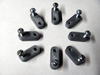
These are what I ended up with to join the blocks that hold the cards. I tried 3D printing the threads but at 8-32 size the threads are not really there. With these I printed the parts with the correct size hole so that I could run a tap through them. They hold very well. The 8-32 screws are from a box of 100 I must have purchased 40 years ago. Period correct screws?
IMG_0296.JPG
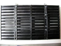
This is three of the blocks connected by the joiners. Each of the blocks takes a little over 4 hours to 3D print. I need 7 for each storage box.
IMG_0297.JPG
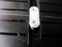
This is a closeup of the joiner in action.
IMG_0298.JPG
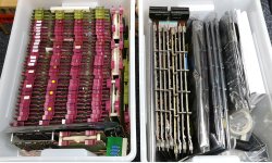
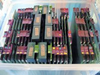
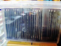
Here is the first box loaded up with cards. The left most cards up to and including the M8320 are the boards that will probably end up in the 8/e. The other cards are extra CPU cards some of which are known to need fixing. This is about half of the quad cards in my collection. There is a working EAE in the cards on the left. There are two 8k core memory sets so hopefully I will have a working 16k in this box.
IMG_0299.JPG
Here is a side view of the "Bankers Box" holding the cards.

Overall I am pretty happy with the way this turned out. I am going to make 7 more blocks to fill a second box and then figure out a hex board solution. These boxes are large enough to hold hex boards in the other orientation.

There were 8 more boards in the DECset 8k than what I am going to put back in it for now. There was a DK8EP (M518 and M860) Real time clock, a KP8E (M849) which is the power fail auto restart module, an M8350 which is a Posibus interface, two M1703s and a M1705 module which are 12 bit interface cards. There was also an unknown card made by someone other than DEC. It might have been the interface to the typesetter. I will post a photo of that later.

I cleaned up a little more of my bench in order to make room for the above mentioned 8/e. While I know the CPU cards work (We tested them in Vince's 8/e) I don't know about anything else that was in the chassis.
 
Loving that Model T and you are somewhat close Mike! Do you head up to Great Lakes Dragaway at all? I'm there alot of weekends in summer. Last year not so much but things are looking good with the human malware being under control by this summer!
 
Nicely done Dough! I have also several of these kind of boxes with 12 and 16 bit stuff...
I have too few PDP's to put all the boards in...


IMG_20211006_201157.jpg
 
2Lazy, If up is considered north, then I would have to go down, to the strip. I spent a lot of time there in the 60's when I was into fast cars. But now I've slowed down a lot. Our Model T Club had our cars at the strip a few years ago. They let us lineup, but could not go down the strip. Our cars leak too much oil. But is was still fun to see the 'fast' cars in the back getting ready for an evening of racing. They have changed a LOT since my time.

I've been working on my IBM XT and have just finished up changing the hard drive with an XTIDE. Had a boat load of trouble, but got around it. It is working good now. Yesterday, I fired up the PDP8E for the first time since last year. No smoke! I loaded up a couple of MAINDEC's from paper tape and all seems well. It is amazing just how much a guy (old guy) forgets when you are away for a few months. Good thing I keep a log, now only if I would learn to write legibly and could hold a coherent thought. But after fumbling around a bit, the MAINDEC's work. I noticed that I do not have a complete library of MAINDEC's on paper tape. So, I'm taking this opportunity to make some progress on completing the library. Mike
 
Trying to correctly re-assemble the 8/e (DECset8k). Here is a photo of the front panel.
IMG_0306.JPG
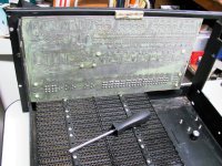
The panel is inserted and the white protector at the top center is in place. There are supposed to be two of those spaced about 1/3 of the way from the edge of the board. The one I have is quite stiff and was very difficult to slip on the edge of the circuit board. I am missing one nylon #8 washer which I will pick up when I go out later this morning. Not so careful inspectors will notice that the base of the cabinet needs cleanup and paint. The white flecks are paper towel debris that wants to stick to the sharp edges of the paint and rust. Painting will have to wait as I can't paint inside and the temps are too cold even in the garage.

IMG_0305.JPG
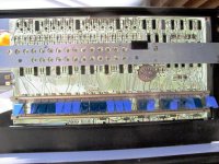
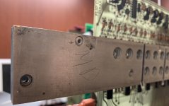
And here is the front side nicely backlit. The aluminum bar serves several purposes. DEC calls it Support Glass on the drawings. On my machine it is four layers of aluminum held together with pop rivets. There are threaded inserts in some of the other holes used to attach it to the PCB with standoffs and to attach it to the frame. It acts as a shadow mask to isolate the light from one lamp to the next and probably as a heat spreader to move the heat away from the lamps. I don't know what the purpose of that piece of Velcro (hook side) is as my front panel is bare in that location. Maybe there was a loop side piece of Velcro attached at one time in that location. Anyone know?

IMG_0300.JPG
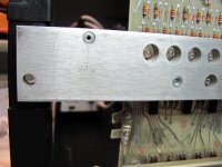
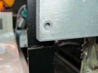
This is my problem area. I am guessing that there is supposed to be a threaded insert on this side of the "Support Glass" but it was missing when I received the machine. I am hoping someone can confirm that there is supposed to be an insert just like on the other end.

IMG_0304.JPG
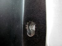
This is the best I can do to show the screw side of that end of the "Support Glass". The rusty marks in the metal show that at some time there was a lock washer here. And there are marks in the hole where maybe the insert pulled free. I am going to 3D print an insert and not overtighten it for now.

More later!
 
Remember the nylon washers next to the PCB for the front panel aluminum stiffener bar standoffs. You can short some of the signal traces on the front panel PCB without the nylon washers, and then PC traces go up in smoke. Ask me how I know.
 
Yes, mine has an 8-32 insert in that location.
Thanks! That was what I was hoping to hear. That is a good photo. I really need to get the tripod out and get a lot more light. Here is what mine ended up looking like using a silver metal grey colored PLA plastic.
IMG_0308.JPG
It is a simple cylinder of 0.25 inch OD with a 0.136 inch ID. The 0.136 is the recommended size for tapping an 8-32 thread. I pressed it into the hole and then tapped the threads. It will pull out if I use excessive force but I like it as a repair and it looks pretty good. A dab of epoxy and it would have required drilling to remove.

Remember the nylon washers next to the PCB for the front panel aluminum stiffener bar standoffs. You can short some of the signal traces on the front panel PCB without the nylon washers, and then PC traces go up in smoke. Ask me how I know.
Mike: Those washers are present and I had already recognized the need for them. I wonder why they didn't use Nylon standoffs originally as that would have eliminated the need for the washers.

I think a helicoil should work for that...
I thought of this. I am trying to figure out what they originally used. Some sort of rivet insert maybe? My other thought was to clean out the hole and then fill it with JB Weld. Drill out a 0.136 hole and tap it. The thing I ended up with took maybe 20 minutes start to finish and I didn't have to leave the house. Not sure why not leaving the house seems like a plus.

I do have to go get a matching 6-32 stainless screw and lock washer so I guess I still have to go out. But that can wait until tomorrow.
 
Managed to get to the hardware store and pick up the hardware mentioned in the previous post. Except it was an 8-32 screw and #8 lock washer. Next is to install the power supply.

This evening I finished up a second Omnibus storage box and filled it with Quad Omnibus cards. Updated my inventory spreadsheet so I can find them.

When going through stuff I realize I have a lot of HEX width boards for the 8/a. I should make another storage solution for them. I thought the box I got was deep enough but it is not. The measurements would lead you to believe it would fit but the measurements are for the outside dimensions of the container. What good is that?
 
I put the power supply back in the case. Adjusted the key switch to fit better in the front panel. Made two trips to the hardware store to get the screws that were missing that hold the power supply in place.

I mentioned in a previous post that I had swapped the front and rear backplanes because the rear one was in better condition. I also mentioned that the power cables were different lengths. When I tried to plug the now front backplane cable into the power supply connector it wouldn't fit. It has the wrong connector! It also was missing one of the ground wires. I moved the cable from the rear backplane to the front. Surprisingly the one that wont fit has a 9 pin connector block with 5 pins installed. They made it fit by breaking off one of the retainer clips on the rear power supply connector. I got a replacement for that housing not realizing what they had done. I will have to order the matching housing and make a replacement power cable with both grounds. There were so many bad and "good enough" repairs done on this machine.

I will take some photos of this tomorrow.

At the moment the rear backplane is not powered or connected to the front backplane.

I installed the necessary cards and sometime tomorrow I will power it up. I am guessing that there is less than a 50% chance that it will work even though I have known working CPU cards. Since I only have one serial port I guess I will have to get serial disk working over the console once I get it to that state. Or get one of the paper tape readers working. Hmm. I don't have an 8/e diagnostics, only the ones for the Straight 8. I guess I could punch a set on the Straight 8. But I am getting ahead of myself.

More news tomorrow.
 
Doug,

This is a really useful thread to me as I will be following in your shoes presently with my 8/E. I am taking copious notes!

Thanks for sharing your journey...

Dave
 
This is a really useful thread to me as I will be following in your shoes presently with my 8/E. I am taking copious notes!

Thanks for sharing your journey...
I hope your E does not have as many physical issues as this one. Ham fisted service.

Actually the 8/e is easy compared to one mainframe I worked on. That was a CDC 3400. It was mid 1980's and the machine had been retired from service at the local engineering college. The machine was sold for scrap at 12 cents a pound. Before it was loaded on a truck someone thought it would be a good idea to take the core memory power supplies and grab a handful of wires on the backplane and pull. The backplane was hand wired with point to point connections hand cut to length and crimped to tapered pins that were pushed into the back side of the card connectors. Fixing the wiring took around 80 hours and at the end of that time I could manually put instructions into the Instruction register and single cycle step and watch it execute. But we gave up on it at that point deciding that replacing the 400hz power supplies for the core was not going to be practical or reliable. long term. That one made me a little sad. I had been told that only 8 CDC 3400's had been built and that one was probably the last one. I wasn't sad for too long as my next mainframe was a CDC Cyber 174 which I kept in service for a couple of years. The PC revolution is what put an end to that one.
 
I wasn't sad for too long as my next mainframe was a CDC Cyber 174 which I kept in service for a couple of years. The PC revolution is what put an end to that one.
Doug,

I didn't realise that you too were working on CDC CYBER mainframes. :)
I worked on a dual CDC CYBER 175, CYBER 170/720 and CYBER 810 over a period of about 10 years (actually 1977 - 1988).
Starting in 2002 I wrote an open-source emulator for the CDC 6000 and CYBER series. The emulator runs the NOS 1, NOS 2, COS, SCOPE, KRONOS and NOS/BE operating systems.
The emulator running on a modern PC runs faster than the CYBER 175 "supercomputer" did back in its glory days. :)
Contact me by PM if you want to know more.

cdc175-con2.jpg

Regards
Tom
 
After thinking about it more I decided to pull the 2nd 8k core out just in case something terrible should happen. There were two different core memory options available for the E, F, and M chassis. A 4k 3 board set (MM8E) and an 8k 3 board set (MM8EJ). I don't have any of the 4k sets and only have two of the 8k sets. The boards consist of G233E which is the 8k X-Y drivers. That board is connected by two of those pesky top blocks to the H212 8k memory stack. The third board is the G111 Sense Inhibit board which is also connected to the H212 by two top blocks. There are two ways the boards can be placed in the backplane. Both will work but the memory stack must be the middle board or the top blocks cannot be connected. The other thing that must be correct is the memory stack board has to be plugged in to the bus correctly. It can be inserted upside down. Both of my card sets were assembled wrong with the bus side assembled up. On this particular card the only connections to the Omnibus are to the ground pins. I don't yet know what happens when you plug these in upside down and power it up but I suspect I get to deal with the aftermath if it is bad. It is always possible that I accidently flipped them when I pulled the cards to clean everything. That is what I am hoping is the answer but I don't think this is what happened. Now I am gun-shy about turning it on. I will have to think about this and if there is anything else I need to check. I also need to take some photos to post.
 
Back
Top