• Please review our updated Terms and Rules here

What did I do to my PDP-8 today.

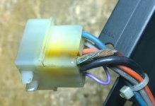
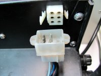
This photo is of the rear power connector and matching cable I mentioned in a previous post.
IMG_0315.JPG
It is kind of difficult to imagine that I never noticed this before. And it actually does work to deliver power to the rear 20 slots of backplane. Ignore the hex head screws just to the right of the connector. I am trying to.

Well, I went out to get some lunch and then do my daily walk and when I got back I could think of nothing else that needed checking so I plugged it in, flipped the breaker on and turned the key.

No drama! load address works and all bits of the PC work. pressed examine a few times and there is stuff in memory. Do it again and the same stuff comes back so memory is mostly working.

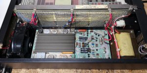
At 200 I deposited a 5200 and then made sure it was there. YES! Load address, clear, continue, and it is doing a JMP to 200. Amazing. Changed the program to a 7001 followed by a 5200 and that works too. That is an IAC followed by a JMP back to the IAC. I can single step and watch the AC increment. For all the problems with the physical stuff the CPU seems to be mostly working. Here is a current photo.
IMG_0313.JPG
Here is the card loadout by slot.
  1. Front Panel
  2. M8330 Timing board
  3. Empty reserved for M8340 EAE
  4. Empty reserved for M8341 EAE
  5. M8310 Major Registers control
  6. M8300 Major Registers
  7. Empty reserved for M837 Extended Memory and Time Share control
  8. Empty reserved for M847 Hardware Bootstrap loader (Roland's version)
  9. Empty reserved for M8655 Terminal control. Console (and eventually the single port Serial Disk)
  10. Empty reserved for M8357 RX01/RX02 interface
  11. Empty
  12. Empty
  13. M849 RFI Shield
  14. G111 Sense Inhibit for 8k core
  15. H212 8k memory stack
  16. G233 8k core X-Y
  17. Empty reserved for second G111
  18. Empty reserved for second H212
  19. Empty reserved for second G233
  20. M8320 Bus Loads
The cards to the right of the power connector are some of the ones for the reserved slots. Since that isn't powered or connected to the front backplane it makes decent storage.

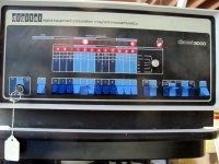
Here is a photo I took of the front panel while it was running the IAC loop at full speed.
IMG_0316.JPG
The front panel faceplate has a red filter on the bulbs. This one is bulbs, not LED's. I would prefer white but this is perhaps the rarest of the front panel graphics for an 8/e.
I see that the time I spent positioning the power switch was wasted once I tightened up the screws. The key is the spare from my Straight 8 I had made at a local locksmith for a couple of dollars. It always surprised me that all the machines have the same key.

Next is to put the M837 in place and verify I can reach Field 1. Then I will move the second 8k into place and verify that works too. Then it will be getting a console interface up so I can feed diagnostics to it.
 
Sweet!

I have two full bags of 9-way connector shells and pins, but I am resisting the temptation to do the same ‘modification’ (aka bodge, hack, butchery etc.) on my machine! Unfortunately, the usual UK suppliers are sold out of 6 way shells for the time being. I will ask around at the smaller suppliers.

Dave
 
I have two full bags of 9-way connector shells and pins, but I am resisting the temptation to do the same ‘modification’ (aka bodge, hack, butchery etc.) on my machine! Unfortunately, the usual UK suppliers are sold out of 6 way shells for the time being. I will ask around at the smaller suppliers.
I would much rather they had drilled a hole in the 9 pin housing than break off the locking tab on the 6 pin. You can probably cut a hole in the 9 pin housing in just the right place and still have the locking tab hold that side in place. Until you can get some six pin housings that seems like a reasonable option.

Before calling it a day, I moved the M837 into place and tested that field 1 is accessible. I also did a manual address test just to make sure all 12 bits are being decoded. It doesn't mean they are being decoded correctly but they all individually go someplace different than the neighbor bit. The last thing I did was install the second 8k. I have not tried it yet. Sometime later today. Then the M8655 needs to be checked out.
 
Doug, you made some good progress and had to deal most with mechanical issues.
Hopefully the remaining boards will work as well without any need for debug & repairs.
Switch 4 looks wrong. What happend to it?
 
@Doug G

"It is kind of difficult to imagine that I never noticed this before. And it actually does work to deliver power to the rear 20 slots of backplane."

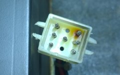
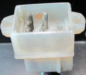
Well, I've made comments about these connectors in the past... This was the power connector in my 8/M.
Also a 20 slots, the machine wasn't even fully loaded with boards. :rolleyes:

03.jpg04.jpg
 
Tried out the 2nd 8k memory board and that passes a cursory test as well. 16k 8/e at least until I find something actually wrong.

Roland,

I didn't realize an 8/m used a different connector on the power supply. Perhaps that is where they got the housing and just moved the pins around. I guess I better look that up.
The red wire with the insulation burned off is the +5? Looks like it got a bit toasty. The black is probably the ground and it looks like it is maybe 14 gauge?
That style and size of pin when brand new will only carry about 15 amps, 20 in a perfect world.

I installed one of Rolands M847 boards and got it working. Now I can quickly feed binary tests into the machine once I get the M8655 working. The M847 came from Jack Rubin. Thanks Jack!

Tomorrow I get to tackle the M8655
 
I didn't realize an 8/m used a different connector on the power supply. Perhaps that is where they got the housing and just moved the pins around. I guess I better look that up. The red wire with the insulation burned off is the +5? Looks like it got a bit toasty. The black is probably the ground and it looks like it is maybe 14 gauge? That style and size of pin when brand new will only carry about 15 amps, 20 in a perfect world.

The pin types in the connector are probably the same. When new, the contact resistance was very low. But after years oxidation and less contact pressure can rise the contact resistance. This can generate massive heat. The red wire was the +5V indeed. I have put an extra set of wires for GND and +5V from the 5V capacitor on the power supply directly to the back plane. So now the wires are double. I've done the same in my 8/F and also in my low model PDP11/10. Never had any problems again.

When I see your picture I think I see the also a little oxidation...

connector Doug.jpg

Here is my 11/10, it has the same power supply as the 8/F or 8/M. I've added an extra set of wires between the 5V capacitor on the power and the backplane. Originally I had a voltage drop of 0.7v between the power and the backplane. When I added a card I had to adjust the power supply. That is not what you want. Now the 5V is rock solid on the back plane...

IMG_20200710_211800.jpg
 
It appears the M8655 that came with the 8/e works. It was configured for 300 baud 8N2 and I changed it to 9600 baud.

Stole the cable off of the M8655 in my 8/a that was used for Serial Disk and found a USB serial port and it echoes characters like a champ!
 
It appears the M8655 that came with the 8/e works. It was configured for 300 baud 8N2 and I changed it to 9600 baud.

Stole the cable off of the M8655 in my 8/a that was used for Serial Disk and found a USB serial port and it echoes characters like a champ!
Wow - your Decset 8000 (PDP-8/e) adventure did not involve any debugging and fixing of boards. I was not that lucky with my LAB-8/e, but then again you missed out on all the fun I had. 😉
 
Wow - your Decset 8000 (PDP-8/e) adventure did not involve any debugging and fixing of boards. I was not that lucky with my LAB-8/e, but then again you missed out on all the fun I had. 😉
I haven't run any diagnostics yet. Now that the M8655 is believed to be working I should be able to feed it some diagnostics. I also have not installed the EAE although the ones I am going to put in it were tried in Vince's 8/e a little over a year ago.

I doubt that there is any chance that I won't get to fix something in the electronics. And if you rewind I did have to solder a resistor back into one of the power supply boards when it fell out of the board onto the bench. That was almost surreal as I had never had a part just fall off a board before.
 
@Doug G

"It is kind of difficult to imagine that I never noticed this before. And it actually does work to deliver power to the rear 20 slots of backplane."

Well, I've made comments about these connectors in the past... This was the power connector in my 8/M.
Also a 20 slots, the machine wasn't even fully loaded with boards. :rolleyes:

BTW, I had to replace some of the power supply connectors in 8/e systems at LSSM recently. Mouser has the parts. Ping me if you would like the part numbers.

-Dave
 
Started running diagnostics. MAINDEC-8E-D0AB which is instruction test 1 ran fine. Its not all that interesting to run because it rings the bell every few seconds and halts on an error. I let it run about 10 minutes.

Next up is MAINDEC-8E-D0BB which is instruction test 2. This one halts at 4315 which tells me the GTF instruction is not working. GTF is an IOT and is the Mnemonic for GeT interrupt Flags. It is an instruction that is part of the KM8E option and is found on the M837 board. I have another M837 which I can try. I will put a red dot on this one for now to indicate it has a problem.

More news later!
 
I found that the GTF IOT is decoded on the M8330 card. I had another that had been tested at Vince's and that one passes both tests. It should be easy to find the problem because the M8330 can be put on a riser and there are only a few gates involved.

More testing tomorrow.
 
I spent several hours this afternoon running Maindecs on the 8/e. Everything is good until I run the extended memory address test 8E-D1FA on fields 2 or 3. Works fine on fields 0 and 1. The failing ones are in the 2nd 8k. As it turns out every address ending in 3 either writes a zero or reads a zero no matter what you try to write there. All other locations appear good. Going to write a little code to find out if it writes to some other address in the field instead of where it is supposed to. The extended address test consists of 4 tests
  1. Write the address at that address in the forward direction.
  2. Write the complement of that address at that address in the forward direction.
  3. Write the address at that address in the reverse direction.
  4. Write the complement of that address at that address in the reverse direction.
The forward tests find all addresses ending in 3 to be zero instead of their address. The reverse tests find all addresses ending in 4 to be zero instead of their address. I can't manually duplicate the address 4 stuff but just writing to 3 fails so I am going to look for the cause of that.
 
Working on the second 8k core issue mentioned yesterday. I studied the prints until I convinced myself the problem is isolated to about 7 components on the G233 8k XY driver board. I pulled that board to inspect it knowing that it was possible the top block could also be at fault in connecting the lines to the core plane. The board is a bit crusty but nothing obvious wrong in the area of the suspect components. I decided to put it back in and run the test again just to be sure and it has been working fine for about 40 minutes now. I really don't like problems that just heal themselves! I will let it run a while more as the room is cooler than yesterday so it could be a heat problem. If it doesn't come back on its own I may get the heat gun out and gently provoke it.
 
I ran the extended memory checkerboard for over 2 hours without a hitch. There is a test for the M837 which I have not yet run. I will run that tomorrow and then grab the heat gun.

As part of the console serial disk I need a timing constant for the TLS instruction. This is so when the handler is entered it can wait that amount of time to be certain any characters sent to the console have completed. The loop looks like this:
Code:
LOOP,    TSF
        JMP NOTYET
/IF WE GET HERE WE GOT A CHARACTER OR THE FLAG WAS LEFT SET.
        
        
NOTYET,    ISZ BDTIME
        JMP LOOP
/IF WE GET HERE WE KNOW NOTHING WAS SENT
On an 8/e (KK8E CPU) this loop takes 6.2us. At 9600 baud with one start, 8 data bits, and 1 stop bit we can transmit 1 character in 1/960 of a second. 1/960/0.0000062=168 loops. I ran that loop on real hardware and counted 0250 octal. 0250 octal is 168 decimal. For giggles I ran the same loop on simh and got octal 031. That is 25 in decimal. Working it backwards that is 6452 characters per second or a simulated baud rate of 64516. I wonder how they came up with that?
 
Back
Top