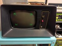
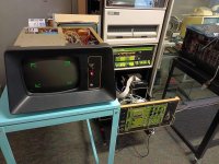
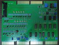
Some time ago I bought a VR14L with extreme screen cataracts.
The VR14L appears to have come from a GT40 setup as on the back of the VR14L there is also a GT40 tag.
Unfortunately I don't have the associated PDP-11/05.
The leaking corrosive PVA glue oozing out between the CRT and the protective front glass had caused a lot collateral damage.
I managed to remove the protective glass, clean up the mess and reattach the glass to the CRT.
Other restorations intervened so I left the cleaned up, but fully disassembled VR14L in one corner of my lab.
Recently I slowly reassembled the VR14L and started a step-by-step checkout of the subsystems.
Power-supply and high-voltage supply all checked out fine.
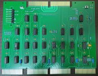
Then I turned my attention to the two A225-YB Deflection Amplifiers.
Without any input one of the A225 drives the output transistors hard causing the VR14L to blow fuses.
The second A225 worked just fine.
I checked the component values near the output and noticed that some resistors were well above their tolerances. The 47 Ohm resistors R23, R25 and R28 are 59, 56 and 57 Ohm. The transistors Q3 and Q4 measured very similar to those on the good A225. Interestingly the bad board uses BD237/BD238 for Q3/Q4 as opposed to 2N4923/2N4920 on the good board. It may be that the transistors Q3 and Q4 on the bad board have been changed sometimes in the past, but the rework is very neat and professional.
I decided to setup an "out-of-circuit" test bed for the A225 using two current limited power supplies for the +/-21V and a signal generator for input to avoid frying the expensive power transistors and/or fuses. With a scope I should be able to probe along the signal path to figure out what is happening.
As usual none of the active components (transistors and op-amps) are readily available. :-(
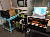
I have then setup a small test bed for the A225 on my work bench.
I supplied power, input and load via an edge connector (2 current limited bench supplies for +/-21V power, programmable signal generator setup for 1V P/P sine wave, 470 Ohm load resistor instead of the deflection coil and a 0.5 Ohm current probe resistor).
This made it easier to compare the working A225 with the faulty one.
I was able to probe along the path of the input signal using a scope and finally figured out that Q2 (2N2904A) was bad on the faulty board.
I did not have a 2N2904A but instead used a similar 2N3467 and now both A225 behave the same and no longer cause the 10A fuse to blow.
Next I will try to get the VR14L fully operational.
Unfortunately it has a W684 (8-level intensity) instead of the W682 (standard intensity) used in the VR14 in my LAB-8/e.
I will have to figure out how to drive a W684 from the VC8E Point-Plot-Boards.
Has anyone tried to use a VR14L with a W684 together with the VC8E Point-Plot-Boards?
A further point of confusion is the G840 Light Pen Option in the VR14L instead of the G838 Fault Protection used in the VR14 in the LAB-8/e.
Does the G840 also provide the Fault Protection implemented on the G838 or is this feature missing when you use the G840.
Finally - is there any way using the Light Pen Option with a PDP-8/e?
Tom