m_thompson
Veteran Member
Don't forget to turn the speaker volume up when KALEID is running.
Wow - blown away!!View attachment 1263031
View attachment 1263032
View attachment 1263033
View attachment 1263034
View attachment 1263035
View attachment 1263036
And some shots of KALEID. For what it's worth, the manuals specify that the horizontal pitch is larger than the vertical pitch, or in other words, the aspect ratio should be rectangular and fill the screen. However, I feel like the square aspect ratio looks better. I guess Vince can decide what he wants to use—right now, it's square, but a single pot on the horizontal deflection amp board in the VR14 can change that.
I suspect we'll look at the broken auto start function and why the START 20 switch is flaky next. Or, maybe see if we can get one working TU55 from three broken ones...
Curious - what can you hear on the speaker of the PDP 12 when KALEID is running?Don't forget to turn the speaker volume up when KALEID is running.
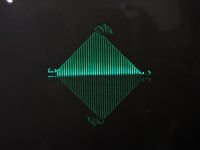
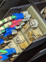
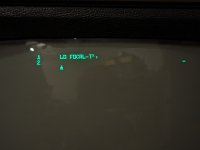
We have never been able to get the LINCtapes to work reliably on the RICM's PDP-12. It will pass all of the logic diagnostics, but will not reliably read a tape. Turn the speaker on when you run LINCtape controller diagnostics. It will make some noises like church bells.We loaded a scratch tape with unknown contents on it and attempted to boot LAP-6/DIAL. The simple bootstrap seemed to successfully pull data off the tape, and starting it running showed us a FOCAL prompt! Mind you, the LINCtape processor and other bits of this side of the 12 had really not been tested since Vince got it. Incredible! Now we just have to learn how to use it since all of us can work our way around OS/8 quite well, but this is a different animal altogether.
 The black stuff is the original foam double stick tape to hold the ribbon cable in place. This was still usable so we decided to keep it. Here is the photo just before soldering the cable back on.
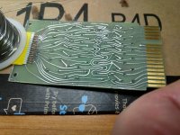 The cable was trimmed with scissors to make a square end just past the delamination area. The difficult part of this whole thing was stripping the plastic off the cable without damaging the copper foils. I could probably do it in an hour now but it took about two hours the first time. The bottoms of the conductors are tinned so it is just a matter of touching the conductors with the iron and then pressing it into the pad below it.
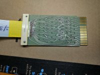 And the completed repair. We didn't have rivets long enough to reattach the strain relief so a cable tie was used. It is not as pretty as I would like but if it works I will be happy. Total time for this repair was about 4 hours. I don't recommend this as a long term repair as the original cable is going continue to degrade. Vince has a kit using modern ribbon cable with IDC connectors and headers which is going to be far easier and reliable long term. We didn't do it this way because we didn't have the kit.
I have several of Vince's boards and male and female connectors and ribbon cable if you need it.While visiting Jack Rubin's Computerarium I got the opportunity to work on his PDP-8i restoration. Since this is not one machine but a collecion of parts it is a little more challenging than some. Vince, Malcolm and of course Jack are all here as well. The power supply was pulled and Jack cleaned that up and reformed the caps. We (me and Vince) tested cards. Of the cards tested we had a very small number of failures, in fact it was only one. We commented on the fact that this was a very high working percentage. This was perhaps 2/3 of the cards.
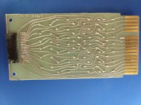
Next issue was damage to one of the cables connecting the front panel switch assembly to the backplane paddle. We stupidly forgot to take a before picture but as many of you know these are flat ribbon cables and the failure mode is the adhesive that attaches the two sides has dried out and they delaminate allowing the conductors to move around causing shorts. In this case the delamination was confined to the last couple of inches at the paddle that connects to the backplane. Here is a photo of the paddle card after removing the cable and cleaning up the pads.
View attachment 1263815The black stuff is the original foam double stick tape to hold the ribbon cable in place. This was still usable so we decided to keep it. Here is the photo just before soldering the cable back on.
View attachment 1263816The cable was trimmed with scissors to make a square end just past the delamination area. The difficult part of this whole thing was stripping the plastic off the cable without damaging the copper foils. I could probably do it in an hour now but it took about two hours the first time. The bottoms of the conductors are tinned so it is just a matter of touching the conductors with the iron and then pressing it into the pad below it.
View attachment 1263818And the completed repair. We didn't have rivets long enough to reattach the strain relief so a cable tie was used. It is not as pretty as I would like but if it works I will be happy. Total time for this repair was about 4 hours. I don't recommend this as a long term repair as the original cable is going continue to degrade. Vince has a kit using modern ribbon cable with IDC connectors and headers which is going to be far easier and reliable long term. We didn't do it this way because we didn't have the kit.
Photos by Vince.
More news later!
Install it in the back of a custom panel van, obviously! A 1974 solution for a 1974 machine!PDP-8/e's are too heavy. If I am going to take big iron to shows I need to find a solution to that.
