• Please review our updated Terms and Rules here

Who knows something about the old NEC PC-6001A around here?

Only had a little while to play with it today but found out that the wire going from CN606 on the power supply was not attached to anything. It looks like it can only go to CN12, but the schematics don't make it explicit that CN606 -> CN12.

CN12 goes to pins 44 and 46 in the cartridge slot, which this Japanese site says seems to be related to hotswap protection for the cartridges:

MSW1 and MSW2 are shorted on the extension board side. Inside the expansion slot, there is a power-off switch, and when this switch is turned on, the power supply of the power supply unit is stopped. In other words, when you try to insert the ROM cartridge into the PC-6001, the power-off switch is physically turned on. The PC-6001 is designed to stop electrically if you attempt to handle it as dangerous as inserting the ROM cartridge while the PC-6001 is operating. If only this is done, the PC-6001 will not operate, but if the MSW1 and MSW2 are shorted on the ROM cartridge side, power supply from the power supply unit is started even if the power-off switch is ON. is. If you insert something thin like a board into the extension terminal, the power-off switch will not turn ON (do not touch the switch), so there is no need to short MSW1 and MSW2.

Although Google Translate has made it more confusing than I want it to be, I think it's saying MSW1 and MSW2 are there to override the reset microswitch in the cartridge slot?
 
It was indeed shorted caps - the tantalums on the 12V and the -12V rail, right next to the PSU connector to the mainboard, were a zero-ohm dead short.

Lucky for me, the RAM appears to be OK so far - I was able to get to the "How Many Pages?" screen.

Unfortunately, the RETURN key doesn't seem to work (so I can't say how many pages) - I'm going to try cleaning it and then I guess see if there's some internal damage to the keyboard. The letter, number and shift keys seem to work.

Thanks for the help! Looking forward to trying this thing out once the keyboard is touched up.
 
Good job finding that. You can try CTRL-M and see if it will accept that is return.
 
That worked great! I wish I had thought of that. Thanks a lot.

I'll do some keyboard cleanup in the next few weeks and hopefully that will make this machine fully usable again!
 
Hope everyone is doing well with their oddball Z80s.

Since the last post in this thread, I've also picked up a PC-6001mkII with an almost completely non-responsive keyboard. My original 6001 has no sound, but I'm hoping it's a dead electrolytic cap in the amplifier circuit. I set up a Japanese tape emulator on a spare Windows laptop and have been playing some games.

Does anyone have a cartridge that they would be willing to measure for me? I'm working on a protoboard since the Japanese protoboard for the system seems difficult to obtain. alank2 is living my dream right now :)

Measurements I think I already have or can figure out on my own, but it would be lovely to have confirmation:
  • Width and spacing of edge connector pins
  • Overall width of edge connector substrate (I'll need to pull the motherboard to get this measurement, but it's coming out anyway)

I'd like these measurements, if you could please provide them:
  • Depth of edge connector pins
  • Thickness of the PCB. I hope it's a "standard" (read: cheap) 1.6mm
  • Width of the rest of the cartridge PCB after it gets wider when leaving the computer
  • Any screw hole positions, although I think it's going to end up a non-standard length

Thanks in advance! So far my plan is to prototype it with paper until I get something that looks right, but it would be nice to have real measurements.
 
SSS see post #20 - I've got an extra cartridge expansion board I can send you if you want to pay for the shipping. It is just a raw PCB, but you can solder a 50 pin connector on it and this allows access to all the cartridge signals. Drop me a PM if interested.
 
I've got a real cartridge too (1 of them) so I can take some measurements with calipers tonight.
 
NEC PC-6001 Canyon Climber Cartridge

width 3.296"
length 4.320"
thickness 0.797"

pcb width 2.870"
pcb length 3.559" (no fingers)
pcb length 4.031" (with fingers)
pcb thickness 0.065" (1.6mm)
pcb fingers width 2.571

fingers pitch 0.100"
fingers width 0.070"
fingers thickness pcb only (no metal fingers) .059"
fingers thickness with fingers on both sides measured 0.066 - each finger may be 0.0035" thick.

there is one hole that lines up with the cartridge case - it is in the middle of the width (1.435" from each edge of pcb).
hole is 0.323" diameter
hole is also 0.880" from edge of fingers to its center.
 
I uploaded it to the Internet Archive as well, hope that's OK alank2: https://archive.org/details/pc6001schematic

A word of warning: I've noticed that the capacitor values are a little off. I/O is an enthusiast magazine in Japan (really curious if there are other computer schematics in the bookazine where this came from) so they're definitely not official NEC quality.

All of the power rails on my Japanese PC-6001 had 22µF tantalums, even though the schematic from this PDF indicated they came in different capacitances. Same goes for the audio circuit which I recently shotgunned caps at before realizing that the volume potentiometer was cracked in half. So definitely check your values before you order any replacement passives, if that is what you are up to. :)

Still, the circuits themselves seem to be generally accurate and the schematic has helped me out so many times.
 
Last edited:
A friend of mine has a NEC Trek board with a dead i8049 MCU. These usually don't go out, but somehow this one did, and we checked the lines.

Can someone with a Trek dump theirs so that we can revive it? MCS-48 should be easy to read nowadays with homebrew devices, and programmers that support the 8749 can support reading the 8049 as long as you're not doing anything other than reading it... :)
 
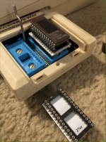
I recently was surprised to find a PC-6006 RAM/ROM cartridge was not too pricy on eBay so I got it.

I found a helpful page with information about it here:

The EPROM pin graphic that Chuck posted the other day was handy and I figured out that each slide switch (not visible in the picture, behind the IC) essentially swap pins 18 and 21 (A11 and A12) for its IC.

I also found some pin adapters PCB's that worked great off of eBay at $3 each. The switches in the PC-6006 should be pushed to the right when viewed from the front of the computer with the board plugged in.

Now I've got some EEPROM 8K IC's (AT28C64B) in there that are easy to program and fill the full 8K address space of each socket.

I was a bit worried about the board overlaying the ZIF socket handle, but there is room to operate the handle just fine.

This picture shows an EPROM before I put the EEPROM in.

I've got extended BASIC working great, next up I'm going to reassemble the NECMON monitor I made to 0x6000 and put it on a second IC so I can have the monitor without loading it from cassette.

1676854302148.png
 
NEC loves their 23 ROMs, the word processors, 88 and 98s are chock full of them.

Nice find, I love the ZIF socket as well. I think there is an assembler rom floating around out there.

9BADD63A-A11E-4CB0-98AF-7FF11F4A092E.jpeg

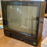
I have been working on the 15” TV/monitor combo that came with the PC-6601SR/MrPC over the last few weeks. It doesn’t power up and I’ve located and fixed at least one shorted electrolytic cap on the standby circuit. Hope to have some cool pictures of it soon as it can decode the 15-colour RGBI output on the PC-6001mkII.
 
Last edited:
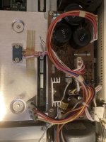
Greetings 6001 aficionados! I recently added one to my collection and am in the process of troubleshooting and repairing. My unit has shorted 12v rails on the logic board similar to others have been reporting. I am in the US and I probed power supply voltages. 5v was a little high and could be adjusted with a variable resistor. My 12v rails were very weird however. I am getting 16v and -13v. It would explain why the 12v rail is shorted I bet those 16v tant caps got fried.

I don’t understand how the 12v rail could be so high. I was feeding the unit 120ac when I took those measurements. I have a step down converter to 100ac and connected the supply up to that. With 100ac the readings are 14 and -12.5.

My plan is to recap the power supply board. Once I get good voltages on it I’ll tackle the 12v rail on the logic board (probably the tantalums others have swapped out as well). Any other areas to check?

IMG_4045.jpeg
 
Last edited:
Hi,
I don't know details about the 6001 but can comment about PSUs in general. Were you measuring the supply outputs with any dummy loads attached? Often you need to draw the rated current from the +5V output (which is normally regulated) which then causes the +12V / -12V outputs (unregulated) to change voltage. Or sometimes need to draw current form the +12V output too.

Regards,
John
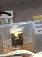
Hey thanks for the response John! No I did not have a dummy load attached when doing those measurements. Looking closer at the board I do not believe the 5v is regulated either. There are two NEC C2373 packages which I had assumed were voltage regulators but they are not. I’ll remeasure again with a load on the 5v rail and see if the 12v comes down. If it does I’ll just proceed to recap the logic board tantalum’s when they come in the mail

IMG_4043.jpeg
 
Back
Top