• Please review our updated Terms and Rules here

Hi, new to the forum, fixing a Commodore PET

This may be the problem. CS0 should only pulse high during the X8XX periods. The line may be open which would indicate about 1.6 volts.
-Dave

But that would sound like that 7425 has something .. or the pullup resistor on the expand input has something odd or the chip itself is odd.

In fact that CS0 now I see again is positive logic so when UNselected it should be a steady '0' not that 2V certainly.

I could try to replace the 1K pullup resistor and see if anything changes, pity that 7425 is quite an unusual chip and in case I should make some 'adapter' and replace it with some other chip.

[edit] Just because it was easy to do I just replaced R49 and R51 with some new ones, however even the old ones I took down they still measure around 1K ( 987 ohm or so but don't trust too much that thing ).

We'll see later if that changes anything, if not it could be that 7425 chip has 'something'.
 
Last edited:
SN7425 is still available from several standard suppliers, including Mouser (and in-stock) and Farnell as well. It's also available in NTE's line of universal replacements as the NTE4251. If you like to order your parts from the Far East, it's also in Futurlec's offerings.

It's one of those ICs for which there really aren't any exact substitutes, yet there is still a demand.

Yes I did check already, I found out is still on sale somewhere, however this means to place an order and wait quite a few days.

If that chip needs removal this still means I have to despised it, put a socket at this point while waiting for the chip to arrive i could so an "adapter" with a couple of other chips ( standard or gates ) to see if it works.

(edit) I am not going to correct the sentences, blame the iPad autocorrector :d
 
Right ..

Changing the resistors did not change anything.

Pin 22 of the PIA show that strange "stable a bit noisy" about 2V thing.

By measuring it with a volt meter it says about 1.56V ..

So I suppose I have to assumne that 7425 is gone ?

What I will do tomorrow I'll take it out and put a socket, I have lot of 74LS32 and some 74LS02 around here I can do an "adapter" and replace it with a couple of chips.
 
I'd lift the output of the 7425 (i.e. cut the lead free from the PCB--you can always bridge it with a bit of solder) before I started pulling teeth just to see if it's the 7425 or perhaps something loading it down. If it is the 7425, then you've lost nothing.
 
I'd lift the output of the 7425 (i.e. cut the lead free from the PCB--you can always bridge it with a bit of solder) before I started pulling teeth just to see if it's the 7425 or perhaps something loading it down. If it is the 7425, then you've lost nothing.
Well, it only goes to the two PIAs which are socketed and the '08, so I'd just pull the PIAs again (especially since plugging them in caused it to go wonky); then it's either the '08 input or it's indeed the '25 output. If it really is the '25 maybe a temporary pull-up or -down resistor on the output would bring the output to a proper TTL level for now.
 
Last edited:
Mike, my eyes are too tired to stare at a blurry schematic tonight--would you happen to know off-hand what the other half of the 7425 is used for?
Looks like part of the DRAM MUX/refresh circuit; bottom left center of page 5 generating BANK SEL signal used on page 6.
 
Ok we are getting somewhere ..

I took the route "away that thing" .. which unfortunately I almost managed to get that chip ( the 7425 ) off completely intact but 2 pins in the end broke.

So while waiting to get a new one meanwhile I set a socket and an "adapter", basically I re-created the 7425 using a 7432 and a 7402.

Finally not that 1.6V and something but 'a 0 as it should be', also my test now runs with and without the chips.

So Yay I burned the Eproms to have the basic in ..

But .. 'there's still something else' .. hum ..

Ok picture number one :

BAD7425_1.jpg


And picture number two, this is where I am now .. note I found out I get there even removing the C000-D000 rom .. but I don't understand now why it's stuck in there ..

Yet is an 'improvement' I never seen that happening before ..

BAD7425_2.jpg


.. the saga continues ..

There was something wrong with that 7425 anyway ..
 
You've hit a BRK instruction somewhere which has dropped you into the monitor program.

Looks like you're finally almost there...
 
The strange thing is there is no flashing cursor no keyboard working ..
Not strange at all, especially if half the ROM code is missing as it is in your picture. Obviously there's something wrong in the firmware or you wouldn't be in the monitor in the first place, so why would you expect the keyscan, cursor, etc. routines to work properly?
 
Now it seems the culprit is UC7 ...

I re-checked firmware and all .. should be OK ..

But then I found out that if I pull out UC7 that's what I get ..

FirstBasic.jpg


However no flashing cursor and no kb working.

I tried to swap one PIA with another, cause there are 2 identical ones ..

No change ..

If I plug UC7 in .. I get the monitor, always with that C* .. etc.

If I UNplug UC7 then I get up to there ..

It's weird and I am not understanding well .. from one side it may look like "it's getting an interrupt and something goes wild" and from the "other side" ( UC7 unplugged ) then looks like "it's not getting any interrupt that's why you don't get that monitor but no cursor/kb ?".
 
Now it seems the culprit is UC7 ...

I re-checked firmware and all .. should be OK ..

But then I found out that if I pull out UC7 that's what I get ..

That is somewhat understandable. Pin 9 input to the C7 is a signal called "diagnostic". If held low on the User Port on power up, the start up code brings the PET up in the Machine Language Monitor. If left alone, it comes up normally. When the PIA is missing, who knows what happens.

Do not worry too much until you replace the 7425 chip. As both NOR gates may be bad causing problems with memory. One thing at a time. You do not want to 'induce' a failure now that you are so close.
 
Last edited:
That is somewhat understandable. Pin 9 input to the C7 is a signal called "diagnostic". If held low on the User Port on power up, the start up code brings the PET up in the Machine Language Monitor. If left alone, it comes up normally. When the PIA is missing, who knows what happens.

Do not worry too much until you replace the 7425 chip. As both NOR gates may be bad causing problems with memory.

But that small thing I built actually "reconstructs" the 7425 in full, both of the 4 input NOR gates not just one, it re-creates 2x4 inputs NOR gates by combining two times 4 inputs into 2 OR gates the output of which goes into 1 NOR gate.

So it's like Q1 = NOT ( ( A1+B1 ) + ( C1 + D1 ) ) and Q2 = NOT ( ( A2+B2 ) + ( C2 + D2 ) )

Or if you prefer it like that :

Q1 = (A1 OR B1) NOR (C1 OR D1)
Q2 = (A2 OR B2) NOR (C2 OR D2)

You got the idea of what I've done.

It looks like it would be getting an interrupt and jumping into a wrong INT subroutine, I am quite tempted tomorrow to make another test program where I load the same interrupt and reset vector that are in the kernal rom, place something at reset that does something on screen and something else that does something else on screen at the IRQ vector.

Then try to give interrupts by hand or something and see if it works.

I am not not "super convinced" yesterday when checking the various BAxx lines some of them were looking 'a bit strange' with like a small amplitude squarewave of some high freq 'over the '1' could be normal, could be shit .. I don't know ..

Could be worth changing the address buffers ? I don't know .. should it look a "well clean" wave of could it have some "spurious" ?

Mah ..

Besides, no expert, how the 6502 recognizes "where the interrupt comes from ?" I suppose it has to check all the possible devices ( some registers ? ) and see which one is the source that generated it and what to do then ?

I don't think in this case you could have something like "wrong interrupt vector on the bus" ? ( apart from the one read from ROM I mean ).
 
Besides, no expert, how the 6502 recognizes "where the interrupt comes from ?" I suppose it has to check all the possible devices ( some registers ? ) and see which one is the source that generated it and what to do then ?

The 6502 only has a primitive interrupt. The interrupt vector must be at FFFE and FFFF in low byte, high byte format and it is up to the interrupt handler routine to figure out what caused it. The non-maskable interrupt would be fetched from FFFA and FFFB but is not used in the PET.

I think the PET only uses an interrupt for the jiffy clock. 60 jiffies per second. I'll have to look into the IRQ service routine.

Edit: A quick look indicates it does a few tasks like blinking the cursor, tape motor monitoring, keyboard scan, and scrolling.
 
Last edited:
The 6502 only has a primitive interrupt. The interrupt vector must be at FFFE and FFFF in low byte, high byte format and it is up to the interrupt handler routine to figure out what caused it. The non-maskable interrupt would be fetched from FFFA and FFFB but is not used in the PET.

I think the PET only uses an interrupt for the jiffy clock. 60 jiffies per second (an interrupt every 16.67 mS). I'll have to look into the IRQ service routine.

We'll have a look at that and we'll do that experiment tomorrow.

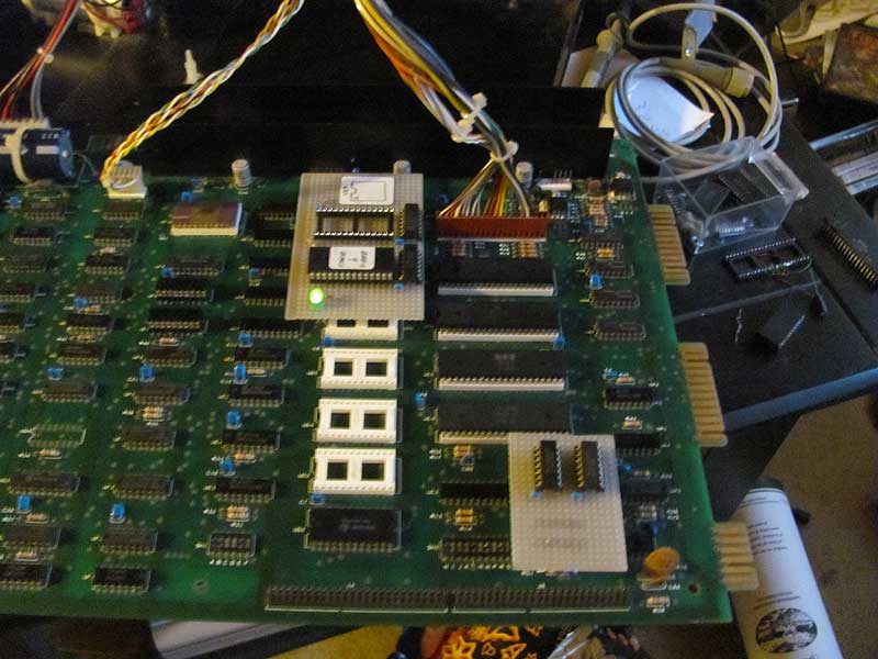
I did check CB1 of PIA1 ( U7 pin 18 ) and you can definitely see a precisely 16.6and something ms 'clock' in, which is certainly is the 60 Hz interrupt.

I don't know if I could simply ( for debug ) connect ( maybe via a resistor better ) pin 18 to pin 37 - IRQ ) and use that as a test interrupt generator for my own test routine. (*)

Funny thing is WITHOUT U7 inserted it NEVER goes into the monitor.

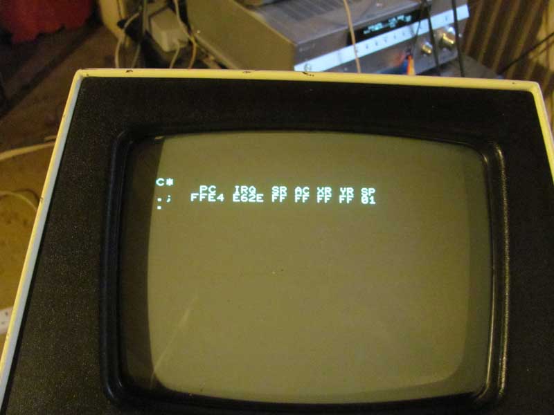
When U7 is inserted it ALWAYS goes into the monitor but it freezes us there.

It's like the cursor flashing and KB scanning routine is never executed.

Now not sure how it works .. let's suppose by absurd the 6520 is faulty .. heck knows what could happen, maybe the program stuck in some loop waiting for something to happens that never does.

But .. both 6520 not working ?

Suspicious ..

VIA not working ? .. don't think so, I have 3 different 6522 chips I can't believe all of the 3 are not working.

Yet the HW seems "so simple" you could say "unless the code is totally crap" how it could even fail to run the correct thing ?

Hum ..

(*) actually probably not because the "vsynch" signal stays low too long, I think IRQ is level sensitive not edge sensitive right ?

If it says low 'too long' by the time my interrupt routine is finished and I re-enable the int I could get an int immediately after instead of 16.6 ms later, you would need to feed that to a S/R latch and have a way to clear it before to re-enable ints.

(edit) I am very tempted to do an experiment that is :

Leave the 6520 out
Put the NMI vector the same of the irq
Connect a wire from the 60 hz int to NMI
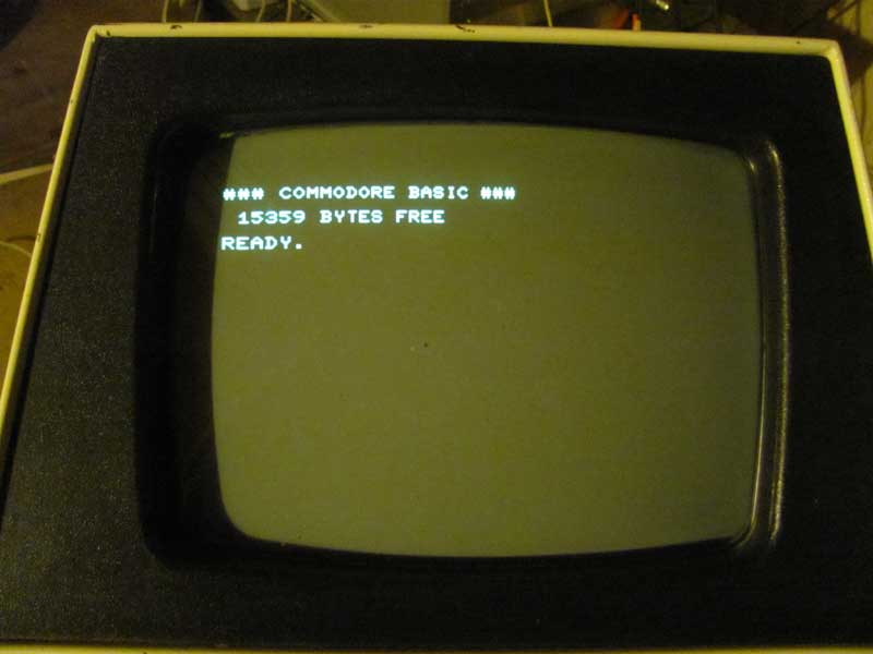
See if I get at least the fashing cursor

Or do the all above with my custom irq thing at the same address to test if interrupts are served ok.
 
Last edited:
We've done 'the crude test' to put the NMI vector at FFFA FFFB the same of the IRQ one.

Then with a wire connected after 'boot' pin 18 to NMI.

It was kinda working, as soon as you do that the Monitor is called but we were also getting a flashing cursor ( of course no KB working cause there are no chips in ).

We are going to do a better test with a program designed to run in the same addresses where the normal IRQ should be using this NMI.

All this seems to prove anyway that for some reason we are not getting any interrupt from the PIA, I did check resistors and connections and all .. it should be all right ..

Both PIAs broken ? .. I don't know .. I have to see if I can find a working PIA somewhere and try to put it in .. sounds quite a bit weird ..
 
Ok .. we almost got it all working .. some lines of the KB seems not to work but for the first time ever we went into basic.

Got another PIA from an Atari 800 .. actually it's a 6520A that for some reason refuses to work ..

However .. I think we found out that probably now 'main cause' it the chip socket istself .. despite tried already more than once the "insert/reinsert chips in/out" with no significant effects after we put this in and that out and such we found out that.

- Its original PIA must be broken, the 'new' one got from a 1541 drive works
- one of the 2 6520 does not seems to work fine
- that 6522 + the other 6520 seems to work but only 'at moments' when inserted in/out a number of times and found 'the correct way in' ( it's seems to be a semi-stable condition ).

I am going to desolder the UC7 socket and put a brand new one in to see if anything goes better.

We managed to run 10 PRINT "HELLO" 20 GOTO 10 but with not all the KB working.
 
Back
Top