• Please review our updated Terms and Rules here

8 bit IDE (XTA) Replacement Project

I thought the FreHD for the Tandy Model 3/4 was doing something like this, but it is not - it uses a one-way shift register for reads. For writes and read setup time, it halts the Model 3/4 CPU.

I suspected they probably did, the TRS-80 bus has a pretty easy to use WAIT line. Not having that facility on this bus is going to make this pretty tight on any MCU that doesn't specifically have a get-out-of-jail-free card like that input port on the PIC32.

(I am still very curious about that PIC's latency for reacting to the "this port was touched" events. On most machines likely to actually benefit from an XTA hard disk replacement if you can react to a value being read or written and update the register in something around the 1-microsecond ballpark that's probably enough?)

This does seem like a great option for a 5v, 40 pin micro. It is a little more costly than a 328, but not much so.

My big AVR project (currently on hold because of real life) started with a 328 and a GAL programmed to be an autoincrement counter for the LSB of a video address but going to the 324 and just using two ports for the MSB/LSB made life so much easier and more flexible. (I can do arbitrary strides through memory just by changing the increments, etc.)

I have a sleeve of these - I was thinking of designing a DMA circuit for old Tandy's.

I think for this project, if we are adding that much external memory, it is time to bite the bullet and use a CPLD.

As Chuck notes if you don't want voltage shifters there's not much in CPLD-land these days. A 74LVC245 might be *fine* even running bidirectionally because the PC bus should react to TTL level output highs, which are spec'ed at only 2.7 volts. Assuming it runs close to the rails like most CMOS devices I would think it should drive the bus adequately with a 3.3v VCC? You'll need 3.3v anyway for the SD card, so if the PIC will do the job it seems like a really attractive option.


Yeah, there are a lot of parts to implement.

I am *not* at all familiar with how fast DMA cycles are on the ISA bus compared to the 8088 cycles (I assume they replicate the T-state counts similarly), but assuming they *mostly* look like normal reads and writes in terms of latency and you can put together a bus interface that can respond to those with adequate latency then maybe the DMA isn't going to be that big of a deal? You'll need some flip-flop logic to assert DRQ and accept a DACK as the signal for the next byte to be supplied/processed, and at the end of the transfer (presumably in a case where you've transferred a full 512 byte sector?) you'll need to fire the interrupt pin. I don't know if that PIC32 will be able to handle that just through GPIO, but it is pretty fast in theory and if instead of using interrupts you switch to a tight polling loop during DMA transfers I'd think this might be surprisingly doable.
 
I did some testing on 8 bit ISA (8237 type, not bus-mastering) DMA some years ago and found, much to my disappointment that maintaining a 1MB/second rate was pretty much the limit. 16 bit 0WS should double that.
 
Is that what the "ACTIVE" line on the bus is for? I can't find docs for that.) That would be a useful feature if a user installed a conventional HD controller instead.

The signal on pin 39 next to ~CS? That is the drive active signal for the activity LED.
 
I did some testing on 8 bit ISA (8237 type, not bus-mastering) DMA some years ago and found, much to my disappointment that maintaining a 1MB/second rate was pretty much the limit. 16 bit 0WS should double that.

I am not super fussed about performance given that the original drives are not all that fast.

I do think I need to do some more testing with different interfaces and machines to figure out worst case timings. I am only getting about 100k/s from my ST351 A/X in my 486 board. I just watched VWestlife's video again and he is getting more than double that in a 286 Tandy.
 
You'll need 3.3v anyway for the SD card, so if the PIC will do the job it seems like a really attractive option.

I was going to use one of the (micro)SD to pin header adapters available on eBay, Ali, etc. for very little money. They include a 3.3v regulator and level shifting to 5v. The full size SD modules do export 3.3v on a pin - might be enough to run the micro.

What environment do you use to program your AVRs?
 
What environment do you use to program your AVRs?

I can hear the booing from the rafters already: I’m currently building my stuff out of the Arduino IDE with the MCUdude “MightyCore” add-ons for bare-metal AVR-ing on bigger chips. I’ve been meaning to port over to Atmel AVR Studio, I actually used that to learn the basics of AVR assembly (which I’m embedding chunks of in my Arduino sketches) and it has a good simulator but inertia is a thing and it’s so easy to mix C and ASM code in the Arduino IDE that I haven’t felt the need to actually get to it.
 
I can hear the booing from the rafters already: I’m currently building my stuff out of the Arduino IDE with the MCUdude “MightyCore” add-ons for bare-metal AVR-ing on bigger chips. I’ve been meaning to port over to Atmel AVR Studio, I actually used that to learn the basics of AVR assembly (which I’m embedding chunks of in my Arduino sketches) and it has a good simulator but inertia is a thing and it’s so easy to mix C and ASM code in the Arduino IDE that I haven’t felt the need to actually get to it.

Same, I have only ever used the Arduino IDE. It has been fine for most small projects and I have been able to do the lower level things I have needed. I find it and a Teensy 2.0/2.0++ great for making test jigs for other projects. I did try to use it for a USB joystick adapter once and things got difficult when I didn't want it presenting itself as an Arduino.

I think I will keep with Arduino for the moment while I am experimenting. I will probably make a board up with a CPLD and an ATMEGA. Is it easy to use the ATMEGA324 with the environment?
 
It seems some 8 bit PICs do have a 8 bit single parallel slave port. There must be some kind of black art to navigating the PIC range because I can't figure out how to select parts that have that feature.
 
The eight bit ones don’t appear to have the addressable version of it, which makes it less attractive for this, but I guess I won’t say that definitively because the PIC ecosystem confusing me is one reason I went with AVR.
 
I think I will keep with Arduino for the moment while I am experimenting. I will probably make a board up with a CPLD and an ATMEGA. Is it easy to use the ATMEGA324 with the environment?

The docs for MightyCore have all the info you need. With just a few components you can set up a 324 so it’s in-circuit programmable with a TTL serial adapter once you get the boot loader on the chip.
 
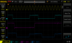
Well.... 286 outperforms 486 in this case. I put the Seagate ST05X XTA card into my TL/2 and did another scope capture. For the fastest code (REPNZ OUTSB), the ~IOW's are only 9 of the 8MHz clock cycles apart. I am going to assume that 10MHz 286's will be 1.25x faster. In the image below, the top trace is the 8MHz CLK and the bottom is ~IOW.

This limits the options a bit. Definitely no serial clocking of the data into a micro. I think 18 AVR clocks would be enough to service an interrupt and read an external 8 bit register through a port. We can control what the AVR is executing while it is waiting for the interrupt. An ATF15xx CPLD Is starting to make most sense to me now since one CPLD and one microcontroller does everything. Microchip are still supplying the software and programmers for these so I think they mean it when they say they are still in production. An ATF1502 with 32 macrocells will probably be sufficient.

I am less keen on trying the PIC32 micros. The 4 addressable registers sound great but we don't know how the micro can respond to the registers being written to. And with at least a GAL and two level shifters, we would have as many ICs as if the CPLD solution was broken out into 3 GAL22V10's.

Also I am definitely not getting a ~CS on the built in XTA bus on my TL/2. This might explain why the original drive stopped working. I assumed the drive was bad but the issue is perhaps on the TL/2 side.

NewFile2.png
 
This limits the options a bit. Definitely no serial clocking of the data into a micro. I think 18 AVR clocks would be enough to service an interrupt and read an external 8 bit register through a port. We can control what the AVR is executing while it is waiting for the interrupt. An ATF15xx CPLD Is starting to make most sense to me now since one CPLD and one microcontroller does everything. Microchip are still supplying the software and programmers for these so I think they mean it when they say they are still in production. An ATF1502 with 32 macrocells will probably be sufficient.

All these calculations are still based on a clock frequency of 20 MHz, right?
The ATxmage devices run at 32 MHz and IIRC the SwinSID SID replacements even use an ordinary ATmega overclocked to 32 MHz. So that would be another option if or when the timing gets a little tight.
 
What environment do you use to program your AVRs?

Since I've still got a parts bin full of various AVR chips, but rarely use them, I use a JDM programmer (hooks to a serial port) and PonyProg under XP. How's that for old-school?

Given the low cost of 3.3V parts with 5V tolerant I/O, I prefer to use a sledgehammer to pound carpet tacks. :)
 
Going the opposite way... could it be possible to add support for 8-bit IDE-XT drives to a modern XT-IDE interface card? The IDE-XT interface cards, like the Western Digital WD-XT150 shown below, are all very simple, with just a few off-the-shelf 74LS-series chips and a ROM.

xt140&xt150.pdf.jpg
 
You know of a working stash of XTA hard drives? At first blush, it would seem to be mostly a firmware issue to support them on an XTIDE.
 
Last edited:
Going the opposite way... could it be possible to add support for 8-bit IDE-XT drives to a modern XT-IDE interface card? The IDE-XT interface cards, like the Western Digital WD-XT150 shown below, are all very simple, with just a few off-the-shelf 74LS-series chips and a ROM.

If you're short on the cards it would probably make more sense to just make a card specific to them than try to double it up on a card that also supports "real" IDE drives. The main problem is the XTA cards want DMA and IRQ lines running straight from the bus to the drive, which XTIDE cards don't do, and the address bits on pins 33 and 35 are 1 and 0 instead of 2 and 1. You could do a mess of jumpers but... there's also the fact that to drive this it'd make way more sense to copy the ROM off of one of the old cards than try to build support for these into the XTIDE BIOS, unless someone also wants to sub the XTIDE BIOS for the BIOS on actual MFM/RLL WD1002-adjacent hard disk controllers. (Which I guess I could imagine a use case for but man, that opens up a can of worms.)

If you really wanted to make one here's my three minute take on how:
  • Start with this schematic: https://www.lo-tech.co.uk/wiki/Lo-te...er_revision_2b
  • Reroute A2 and A1 on the IDE connector to A1 and A0. Also scratch everything on the other side of the connector, it looks like that's entirely grounds
  • Route pins 27 through 31 to the needful bus lines as specified here
  • I think you can ditch that circuit that generates *CS0 and *CS1 from *CS-IDE, just connect that straight to pin 37.
  • Configure the IDE decode '688 so *CS-IDE triggers on 0x320
  • If RESET still needs to be inverted just do it with a 7404 and ditch the '139.
  • Use the flash decode circuitry unmodified, burn a copy of the ROM from one of your existing XTA host adapters into it.
Everything I said above could be wrong, take it with a giant grain of salt.
 
IIRC the SwinSID SID replacements even use an ordinary ATmega overclocked to 32 MHz. So that would be another option if or when the timing gets a little tight.

I've heard the ATmegas are pretty tolerant of overclocking *within reason* if you use a good quality external oscillator. It's on my list to try running a 324 at 25.175 mhz, AKA standard 60hz 640x480 pixel clock, when I can lay hands on the right oscillator.
 
I'd be surprised if you couldn't interface an XTA board to a bidirectional printer port with minimum circuitry. After all, all of these beasties have a sector buffer that can be read and written using PIO. DMA isn't necessary.
 
It mostly comes down to if you want to write your own driver for it. A single 22v10 GAL would probably suffice for the logic on a dedicated board to run it with the original ROM image, if you skip any external buffering that’s two chips.
 
Back
Top