• Please review our updated Terms and Rules here

C64 IN PET S' CASE

Not quite...

You haven't factored the timebase switch setting of 20 [us/div] into your calculation yet have you?

Did you cover Unity brackets at school to check that the units for an equation make sense? You need to obtain microseconds from your equation.

Dave
 
Not quite...

You haven't factored the timebase switch setting of 20 [us/div] into your calculation yet have you?

Did you cover Unity brackets at school to check that the units for an equation make sense? You need to obtain microseconds from your equation.

Dave
🏳️
 
It's quite simple:

0.2 * 20 * 3.5 = 14 us.

Slightly longer than the desired 10 us.

You divide the timebase setting (20 us/div) by 5 (the number of little divisions that the big division is split into) giving you 20 [us/big division] / 5 [little division/big division] = 4 [us/little division].

You have then measured 3.5 little divisions; so 3.5 [little divisions] * 4 [us/little division] = 14 [us].

Does this make sense now?

Now, do the same for the other pins...

Dave
 
I crashed my head into a wall for these for these impossible measures!!
Please where can i insert the other trimmer Dave??? :(
 
They are not impossible measurements. These are basic, fundamental measurement techniques that you HAVE to learn if you want to use an oscilloscope...

We will need to insert trimmers (notice plural) in place of R15 (2.7k) and R11 (10k). These are the resistors that control the pulse lengths of the other monostables - one a delay time and the other a pulse length (if I remember correctly).

However, you will have to do the same as we did with R14 - by inserting a suitable fixed resistor in series with a suitable potentiometer.

So you are going to bang your head into the wall again with selecting the fixed resistors and potentiometers to use.

The fixed resistor needs to be suitable so that winding the potentiometer to one end of the limit does not short anything out - so needs to be 5-10% (or so) of the current value of the associated resistor we are replacing. The potentiometer should be larger than the current value of the associated resistor we are replacing (say by a factor of 2).

The aim is to significantly reduce and increase the variability of the resistance around the current value of the fixed resistor to tweak the timing.

Of course, these potentiometers need to be multiturn devices - so as to achieve the desired accuracy of setting the pulse durations.

Does this make sense?

Dave
yes i understand but i have no multiturn device now :(
 
I have finished my renovation and started to bring order in my "storage". And guess what: I found the original module, including the hand drawn schematic! If interested, I could send it to you, Dave. If not, to Desperado. You'll find my email address on my site.
 
Thanks so much Ruud!! Unfortunately we are changing the scheme because it doesn't work on my 9" monitor. It would be really helpful to receive the original pattern, correct Dave?
 
I bought some multiturn potentiometers on amazon. They ll bè delivered tomorrow!
 
They are not impossible measurements. These are basic, fundamental measurement techniques that you HAVE to learn if you want to use an oscilloscope...

We will need to insert trimmers (notice plural) in place of R15 (2.7k) and R11 (10k). These are the resistors that control the pulse lengths of the other monostables - one a delay time and the other a pulse length (if I remember correctly).

However, you will have to do the same as we did with R14 - by inserting a suitable fixed resistor in series with a suitable potentiometer.

So you are going to bang your head into the wall again with selecting the fixed resistors and potentiometers to use.

The fixed resistor needs to be suitable so that winding the potentiometer to one end of the limit does not short anything out - so needs to be 5-10% (or so) of the current value of the associated resistor we are replacing. The potentiometer should be larger than the current value of the associated resistor we are replacing (say by a factor of 2).

The aim is to significantly reduce and increase the variability of the resistance around the current value of the fixed resistor to tweak the timing.

Of course, these potentiometers need to be multiturn devices - so as to achieve the desired accuracy of setting the pulse durations.

Does this make sense?

Dave
Hi Dave, please what can i do now?? :(
 
What did you buy in the end. You didn't tell us...

Did you buy all the same value, or did you read the post I made earlier?

Dave
 
Unfortunately now i have black screen with new potentiometers!
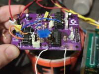
while I was soldering the potentiometer in place of C1, the metal plating on the PCB got ruined... I scratched a bit and soldered but it doesn't work... Now this PCB is a disaster, I'm waiting for my friend Antony to draw me the new diagram and then it is better to order the new PCB with the new changes! I am desperate!
 

Attachments

  • 1694975036584..jpg
    1694975036584..jpg
    2.6 MB · Views: 8
Back
Top