| VCF West | Aug 01 - 02 2025, | CHM, Mountain View, CA |
| VCF Midwest | Sep 13 - 14 2025, | Schaumburg, IL |
| VCF Montreal | Jan 24 - 25, 2026, | RMC Saint Jean, Montreal, Canada |
| VCF SoCal | Feb 14 - 15, 2026, | Hotel Fera, Orange CA |
| VCF Southwest | May 29 - 31, 2026, | Westin Dallas Fort Worth Airport |
| VCF Southeast | June, 2026 | Atlanta, GA |
-
Please review our updated Terms and Rules here
You are using an out of date browser. It may not display this or other websites correctly.
You should upgrade or use an alternative browser.
You should upgrade or use an alternative browser.
C64 IN PET S' CASE
- Thread starter Desperado
- Start date
daver2
10k Member
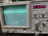
So, what are the pulse lengths then?
Have a go yourself at measuring these - otherwise you will not learn how to do it...
Post your 'working out' as well (so I can see where you go wrong if we don't agree regarding the measurements).
Dave
Have a go yourself at measuring these - otherwise you will not learn how to do it...
Post your 'working out' as well (so I can see where you go wrong if we don't agree regarding the measurements).
Dave
antony
Member
- Joined
- Aug 1, 2022
- Messages
- 31
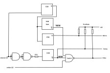
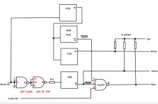
Regards, I designed the VDP pcb. I want to correct the drawing but the directions are confusing, not your fault but the situation is complicated. Hugo's suggestion to replace the 74ls08 with a 74ls10 is wonderful but the PIN numbers of the chip were not written in the drawing, I can deduce it logically but I don't want to make mistakes and I ask Hugo for more details, IC2A-Q connection (pin 13); IC2B-A (pin 9) ; IC3A-B (pin 10). can you confirm ok?
Dave and Hugo you are very good in my little village in the center of southern Italy there is no one like you, I admire you
Dave and Hugo you are very good in my little village in the center of southern Italy there is no one like you, I admire you
Attachments
Hugo Holden
Veteran Member
Hugo Holden
Veteran Member
I'm not 100% sure myself the final circuit configuration that @Desperado ended up with, with all the changes that were required to make it work, that is why I suggested that he looked at it and wrote down and posted what circuit he currently has, so there are no mistakes.sorry hugo, I didn't explain myself well. I need to know the connections for 74ls123 and 74ls221.
the connection between IC2A, IC2B, IC3A, because I noticed a different connection from the initial one
Desperado
Veteran Member
- Joined
- Nov 25, 2017
- Messages
- 7,880
ic2 pin 12 = 20 us???So, what are the pulse lengths then?
Have a go yourself at measuring these - otherwise you will not learn how to do it...
Post your 'working out' as well (so I can see where you go wrong if we don't agree regarding the measurements).
Dave

i am desperate !
daver2
10k Member
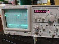
Why are you desperate?
How did you get your 20 us? Please show your working out.
Dave
How did you get your 20 us? Please show your working out.
Dave
Desperado
Veteran Member
- Joined
- Nov 25, 2017
- Messages
- 7,880
White flag for these measurementsWhy are you desperate?
How did you get your 20 us? Please show your working out.
Dave
Too difficult for me sorry
daver2
10k Member
It is not too difficult for you... This is a basic measurement of an oscilloscope and I have previously explained how to do it.
Use the oscilloscope timebase knob to get the [us/div] or [ms/div], align one edge of the pulse up with a major division on the X-AXIS of the oscilloscope using the X-SHIFT potentiometer on the oscilloscope, read off how many major and minor divisions the pulse takes and multiply the timebase knob value by the measurement you took.
The trick is to adjust the timebase knob to maximise the size of the thing you are trying to measure.
For example, if the timebase setting was 20 [us/div] and you measured a LOW time of 3.4 divisions, then the LOW time would be 20 [us/div] * 3.4 [div] = 20 * 3.4 [us] = 68 [us].
You measure the voltages on the oscilloscope by exactly the same method - but you use the Y-AXIS [V/div] knob setting and count major divisions from the 0V/GND reference level.
Work through the problem...
Dave[/div]
daver2
10k Member
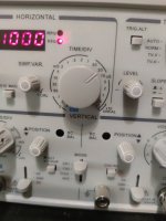
I said previously that IC2 pin 12 should be 10 us and you have 66 us. Is that good or not?
When you mention small squares, what do you mean?
A division is about 1 cm in length on the screen. You may be counting fractions of a division.
Dave
When you mention small squares, what do you mean?
A division is about 1 cm in length on the screen. You may be counting fractions of a division.
Dave

daver2
10k Member
So how many fractions have you got in a full division on the screen?
Dave
Dave
Hugo Holden
Veteran Member
I think one main issue was that the output of IC2A needed to be swapped to the /Q (pin4) rather than Q output (not shown on the previously simplified diagram) , or we could not get any time delay out of it because the Q output rises almost synchronously with the trigger.sorry hugo, I didn't explain myself well. I need to know the connections for 74ls123 and 74ls221.
the connection between IC2A, IC2B, IC3A, because I noticed a different connection from the initial one
If Desperado could look at what he has in front of him on the desk and write down the connections between the IC's, even if the schematic was messy, you could clean it up for him.
Last edited:
Desperado
Veteran Member
- Joined
- Nov 25, 2017
- Messages
- 7,880
Five !So how many fractions have you got in a full division on the screen?
Dave
daver2
10k Member
So each fractional division is 0.2 of a full division.
1 [division] / 5 = 0.2.
This is just like taking a length measurement with a ruler. Where 1 cm is the equivalent of 1 time division on the timebase and the ruler has the cm marks divided into 5 - so each minor mark is 2 mm.
Dave
1 [division] / 5 = 0.2.
This is just like taking a length measurement with a ruler. Where 1 cm is the equivalent of 1 time division on the timebase and the ruler has the cm marks divided into 5 - so each minor mark is 2 mm.
Dave