• Please review our updated Terms and Rules here

Cbm 2001 Pet strange boot

Well,

I think I am calling this repair I am afraid...

We seemed to be getting inconsistent results previously (with different data on the data bus of the EPROM and it differing on the data pins of the CPU socket) - and this didn't seem to be helped by an EPROM not returning the correct data for some reason either when it should have been.

I still suspect something is causing the selected data requested by the CPU not to be read correctly by the CPU - causing the unpredictable results. Sometimes, this can 'work' statically (i.e. by doing what we have done and replaced the CPU by wire links on the address bus) but they can also fail in a 'dynamic' mode (and this was what we were trying to check with the oscilloscope).

Unfortunately, I don't think your oscilloscope skills are that advanced yet.

I think this is a relatively simple problem - it is just there are still too many variables.

The one that most concerns me is that the test firmware that you have should be considered a 'tool' and they shouldn't be just programmed on the fly. You should only be using tools that are known to work correctly. If you need to program a new tool - you should (ideally) ensure that it works on a known good PET before using it on an unknown machine. This (of course) is the 'ideal' solution.

Hopefully, your friend will be able to provide some useful input to this fault. Let us know if you get it repaired and what was wrong.

Dave
Dave but it's correct insert your pettester on ud9 socket? Can i try to use on 2716 eprom in ud8?
 
Again - it depends on which version of the PETTESTER you are using. This is why I am saying that you need to understand what you have got and which socket it goes in.

If you have my 'original' PETTESTER it goes into the EDIT ROM socket (on a 2K ROM) - and you will require the original PET Kernal ROM in UD9.

If you are using Nivag's version - it fits into a 4K ROM in UD9.

If you put the wrong device into the wrong socket it won't work - not because the PET is faulty, but because you are using the tool incorrectly.

Dave
 
in any case I have tried them all and it never worked ... there must be something wrong ... maybe broken tracks ... I will try to send it to my friend. For now, thank you very much ... I'll keep you updated! a hug!
 
You guys have gone above and beyond the call of duty.

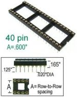
Desperado, did you say a few messages ago that you still have the original white socket for the C4 6502 CPU? That is not good especially when you were still learning to use the scope probe and all the times you inserted a NOP Generator. Commodore used cheap sockets that can cause intermittent connections.

Before you turn the board over to your friend, do him a favor and replace that socket with a good high quality socket. See photo below. Good luck with your PET.
-dave_m

hws2632.jpg
 
My offer of a repair remains but you would have to pay insured postage to and from the UK, cost of replacement ICs/sockets/connectors and a small charge for my time if it takes >3hrs.
Go for it despo, it shouldn't be too much to send a well packed board and it would be a shame for this puzzle to end this way.
 
Before you throw in the towel (and notwithstanding Nivag's very kind offer) - might it be worth asking Desperado to meter for continuity of ALL of the UD9 pins including the power pins?

We had a case (on another forum, with ScottishColin's PET) where we had similarly baffling and inconsistent results while trying to make sense of what was on the data lines.

Eventually Colin realised that there was no connection between the UD9 socket's GND pin and actual circuit ground. The socket had been replaced in the recent past and it was possible that track damage had occurred at that time. When the UD9 socket GND pin was jumped to nearby circuit ground with a soldered link wire, things improved quite a lot.

Ironically, we had asked Colin to measure all of the supply rails to ALL of the RAMs but had stopped short of asking him to do that for every IC on the PCB. If we had asked him to do that he would have been down on that fault much quicker. I'm not suggesting (for the moment) that Desperado measures the supplies directly on the supply pins of every single IC on the PCB, but certainly on the supply pins of the UD9 device, if that has not been done recently.
 
My guess is here, that likely the problem is in the read/write control circuitry as there was a suggestion of data bus interference in the recent round of tests. It would be well worth checking that support circuitry (gates) around the CPU that receive and deploy the R/W signals and both the data bus buffer IC's. Remember IC A4 with two input pins internally shorted. Some destructive currents caused that and probable damage to other IC's in this region. The only obvious thing I think could have done that would have been an accidental transient input-output short of the 5V regulator supplying this section of the pcb. At one point, prior to this destructive event, it was running with the Pettester (post #343) and it booted to BASIC post #572 . But also, it could be a number of other issues. So it will be good to finally find out what was actually wrong, if Nivag could get his hands on this board.
 
Last edited:
This is also why I deliberately asked Desperado to measure the supply voltage between pins 12 and 24 of UD9 - to make sure there was a 0V connection. However, this doesn't mean it is a good current conductor of course.

+1 Hugo. We never found a 'smoking gun' anywhere, so I wasn't really surprised when the machine didn't work. I too think there is a (partially) faulty IC somewhere, but we never came across it in our investigation I am afraid.

Dave
 
thank you all but this morning the card is playing .. I hope that this friend of mine will be able to identify the fault ... I will let you know as soon as I have updates!
 
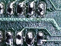
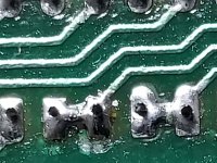
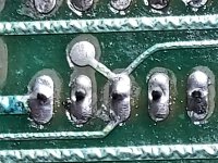
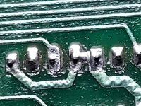
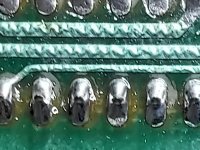
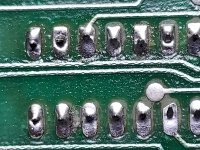
Good evening everyone, my friend received the board and started to check it .... he told me these solders may have problems!! I am desperate!!
 

Attachments

  • 1659115893489.jpg
    1659115893489.jpg
    395.8 KB · Views: 19
  • 1659115893508.jpg
    1659115893508.jpg
    237.6 KB · Views: 14
  • 1659115893542.jpg
    1659115893542.jpg
    255.9 KB · Views: 14
  • 1659115893566.jpg
    1659115893566.jpg
    262.2 KB · Views: 14
  • 1659115893598.jpg
    1659115893598.jpg
    222.3 KB · Views: 19
  • 1659115893631.jpg
    1659115893631.jpg
    363 KB · Views: 19
So we need to realign your mental model with what 'good soldering' looks like :).

Some of this was in the links I posted for you to read.

Dave
 
They don't look too bad to me.
Yes.

It is hard to tell from those photos too, because of the light shadows near the pins, so it is not certain if that is very bad soldering or just the photo making it look bad.

Probably there is more to the fault/s than bad soldering alone.

Though a few of them look like the IC (or socket pin) was not heated enough for solder to flow onto it. One of the biggest causes of that is the person not understanding that the heat from the iron tip needs to be applied to the work with the iron and the solder applied to the heated work. But in error they apply the solder to the iron tip and it doesn't tin (coat) the work. This is also aggravated if there is moderate oxidation of the surfaces of the work, such as the IC pin.

It also helps to have good solder like Ersin Multicore, sold under the Loctite brand in the USA I think.
 
Last edited:
Back
Top