- VCF South West - June 14 - 16, Davidson-Gundy Alumni Center at University of Texas at Dallas
- VCF West - Aug 2 - 3, Computer History Museum, Mountain View, CA
- VCF Midwest - Sept 7 - 8 2024, Schaumburg, IL
- VCF SoCal - Mid February 2025, Location TBD, Southern CA
- VCF East - April 2025, Infoage Museum, Wall NJ
-
Please review our updated Terms and Rules here
You are using an out of date browser. It may not display this or other websites correctly.
You should upgrade or use an alternative browser.
You should upgrade or use an alternative browser.
Cbm 2001 Pet strange boot
- Thread starter Desperado
- Start date
Desperado
Veteran Member
- Joined
- Nov 25, 2017
- Messages
- 6,827
Nothing changes! D3 is always different from others!!Pin 13 is D3.
Turn the timebase down two or three more steps and look again at all of D0-D7, with the timebase kept at the same (lower) setting for all of them.
 ((
((Nivag Swerdna
Veteran Member
Actually I use one of these... https://www.ebay.it/itm/183686874231 which gives 16 channels. It's not easy to configure but works pretty well once it is working. Shows traces in the digital domain.how do you use this?
https://community.infineon.com/t5/K...sing-Open-Source-sigrok-PulseView/ta-p/252866
SiriusHardware
Veteran Member
Nothing changes! D3 is always different from others!!
Could you please show us D0 and D3, both at the slower timebase speed, so that we can see them too.
Desperado
Veteran Member
- Joined
- Nov 25, 2017
- Messages
- 6,827
This not possible! Because with the slower timebase speed (0,5s) i can't see any waveformCould you please show us D0 and D3, both at the slower timebase speed, so that we can see them too.
I am desperate!!!!SiriusHardware
Veteran Member
Sorry, I think you misunderstand me when I say 'slower', I do not mean SLOWEST, just SLOWER, like 20mS or 50mS.
Can you show us D0 and D3 at 50mS?
Can you show us D0 and D3 at 50mS?
SiriusHardware
Veteran Member
Nivag, I think the problem with analysers is that the inputs only see logic '1' above a certain threshold and logic '0' below a certain threshold, they don't display the true state of a signal which on a faulty machine could be at half-levels or intermediate levels. What we really need is an 8 channel (or more) scope (joking, if they exist they would cost a fortune).
Analysers are great for following / capturing what is happening on a 'healthy' system with known good logic levels, but not so much for what Desperado is trying to do here.
Analysers are great for following / capturing what is happening on a 'healthy' system with known good logic levels, but not so much for what Desperado is trying to do here.
Last edited:
Hugo Holden
Veteran Member
Desperado: Dave mentioned this before;
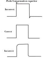
On your recorded waveforms there is peak or overshoot on the waveform's rising edge and when it falls an undershoot, appearing to peak below zero volts.
This is because the scope probe assembly, versus the scope's input capacitance, is not correct and there is a peak in the high frequency response. So those voltage overshoots you are seeing are not really there. Sometimes though, the frequency response can be altered with a long length of wire in series with the probe tip or probe earth too.
On the probe's plug, there will normally be a small hole to access a trimmer capacitor (small variable capacitor).
When a scope probe is married to the scope for the first time, the scope probe is normally clipped onto a calibrator test point (often on the scope's front panel sometimes on the rear) that has a fast rise and fast fall 1kHz square wave. And the small capacitors on the probe's connector are adjusted to make the shape of the square wave as rectangular as possible just after the rising and falling edges of the wave and eliminate those peaks. (see attached image)
If there is no calibration square wave on your scope you can find, you could adjust the probe's trimmer capacitor using one of the waves from the pet, it won't be 100% accurate but it will be a lot better than what you have now.
Attachments
Last edited:
Hugo Holden
Veteran Member
Nivag, I think the problem with analysers is that the inputs only see logic '1' above a certain threshold and logic '0' below a certain threshold, they don't display the true state of a signal which on a faulty machine could be at half-levels or intermediate levels.
I think that is correct for a lot of them. The square waves they display have high and low levels which are generated by the instrument itself, so the waves look perfectly normal and rectangular, even when there can be all sorts of issues on the high and low parts of the signal that are not displayed. Also they won't report the anomalous logic level of something like a bus contention, they will report it as either logic high, high or low, depending on its exact value.
Though it might not be the case for types though. I have seen a design where simply a DC level was switched (added) to each channel and each channel passed by an analog switch (not a logic gate), so the analog (linear) information about the wave was retained, but they appear at different vertical levels on the scope screen.
So with these sorts of instruments that is a thing to check out.
Last edited:
daver2
10k Member
+1
Dave
Dave
Desperado
Veteran Member
- Joined
- Nov 25, 2017
- Messages
- 6,827
Thanks! I checked both probes and are ok!Desperado: Dave mentioned this before;
On your recorded waveforms there is peak or overshoot on the waveform's rising edge and when it falls an undershoot, appearing to peak below zero volts.
This is because the scope probe assembly, versus the scope's input capacitance, is not correct and there is a peak in the high frequency response. So those voltage overshoots you are seeing are not really there. Sometimes though, the frequency response can be altered with a long length of wire in series with the probe tip or probe earth too.
On the probe's plug, there will normally be a small hole to access a trimmer capacitor (small variable capacitor).
When a scope probe is married to the scope for the first time, the scope probe is normally clipped onto a calibrator test point (often on the scope's front panel sometimes on the rear) that has a fast rise and fast fall 1kHz square wave. And the small capacitors on the probe's connector are adjusted to make the shape of the square wave as rectangular as possible just after the rising and falling edges of the wave and eliminate those peaks. (see attached image)
If there is no calibration square wave on your scope you can find, you could adjust the probe's trimmer capacitor using one of the waves from the pet, it won't be 100% accurate but it will be a lot better than what you have now.
SiriusHardware
Veteran Member
OK, so that is still a little bit slow. Try again, D0 and D3 this time at 20mS. This is what Dave meant, trial and error, you have to look at the signals at various time settings to get a 'feel' for whether the signals look right. This is something you will eventually get used to.
Last edited:
Desperado
Veteran Member
- Joined
- Nov 25, 2017
- Messages
- 6,827
Ok this is 20ms:OK, so that is still a little bit slow. Try again, d0 and D3 this time at 20mS. This is what Dave meant, trial and error, you have to look at the signals at various time settings to get a 'feel' for whether the signals look right. This is something you will eventually get used to.
SiriusHardware
Veteran Member
In those captures we are starting to see that there is not actually much difference overall between D0 and D3, they are about the same height, they are active and inactive for about the same length of time. Look at D0 and D3 once more, this time at about 2mS.
Desperado
Veteran Member
- Joined
- Nov 25, 2017
- Messages
- 6,827
In those captures we are starting to see that there is not actually much difference overall between D0 and D3, they are about the same height, they are active and inactive for about the same length of time. Look at D0 and D3 once more, this time at about 2mS.
SiriusHardware
Veteran Member
So again, D0 and D3 are looking quite similar and we can see some very square looking edges in there. Staying at 2mS, now look at D1, D2, D4, D5, D6, D7 - no need to post videos of them, but just look to see if they also look about the same as D0 and D3 and report back.
Desperado
Veteran Member
- Joined
- Nov 25, 2017
- Messages
- 6,827
Yes, i have same waveform in every pin!So again, D0 and D3 are looking quite similar and we can see some very square looking edges in there. Staying at 2mS, now look at D1, D2, D4, D5, D6, D7 - no need to post videos of them, but just look to see if they also look about the same as D0 and D3 and report back.
SiriusHardware
Veteran Member
From those observations we can say that there is probably no physical problem on the data bus, for example none of the lines are shorted to 0V or stuck high, and none of the data line signals look significantly deformed or 'wrong' and they are all about the same size. There are further tests which could be done to be more sure of this.
I will be going out for the day shortly, we have a rare warm day here in the UK and I don't want to waste it, so this is a good time for me to hand the controls back to Dave, Nivag and Hugo. Thank you for working through those tests so patiently. If you continue to do this and do exactly what Dave and the others ask you to do, you will eventually get your machine working.
I will be going out for the day shortly, we have a rare warm day here in the UK and I don't want to waste it, so this is a good time for me to hand the controls back to Dave, Nivag and Hugo. Thank you for working through those tests so patiently. If you continue to do this and do exactly what Dave and the others ask you to do, you will eventually get your machine working.