• Please review our updated Terms and Rules here

Commodore 3016 scrambled screen

I am now waiting for a spare part of my 8016 which i used in the 8032. After that the 3016 is working again, and then it's easier to have a reference.
Then i can meassure a pin on 3016 and see how it's look like on 8032.
 
There is something wrong with your pin numbering (or the signals themselves).

Also, one pin appears to have double the frequency of the rest - which is illogical. This could happen. Or, more likely, you have changed the timebase for this reading. I can't tell, because I can't read the timebase setting on the photographs on my phone...

Pins 9 and 12 should have exactly the same signal (NEXT) on them.

Pins 10 and 13 should be HIGH.

The following pin pairs should also have exactly the same signals on them:

1 and 6.
4 and 5.
3 and 8.
2 and 11.

In addition, the following pin pairs should have the same signals on them, but in anti-phase to each other:

2 and 3.
8 and 11.
5 and 6.
1 and 4.

You don't need to post ALL of the waveforms for these signals.

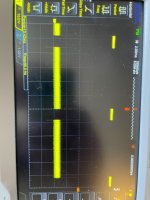
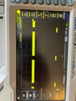
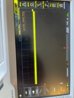
But I would be interested in the waveforms on the following pins:

9, 2 and 6.

Please make sure we can see two (2) cycles of each signal on the trace and the frequency/period is clear.

Dave
 
Well, now you have found G11 faulty, you need to work back from G10 pin 11 and H8 pin 12 to start with.

Then G8 pins 11 and 12.

Dave
 
G11 Was defect. After replacement i now have one horizontal line. So no more screen as in #171
It doesn't make a lot of sense though. I cannot see yet how if G11 was defective it could have altered the timing of the V.drive signal.

Now G11 is replaced, there is clearly no V.drive signal at all, as you have a horizontal line. This suggests, that perhaps, something else went awry when G7 got replaced and, that probably, the original fault remains. ("the target remains" like on the movie Independence Day, after they threw the nukes at the Aliens and waited for the smoke to clear)
 
These Logic ic's are 100% defect.
G11 74LS20 (Now Replaced)
H11 74LS93
F6 74LS157

Now i wait for some spare parts so i can measure the 3032 and compare it with the working 3016.
Now i swap it from the 3016 but i want to keep this one in working state.
 
It doesn't make a lot of sense though. I cannot see yet how if G11 was defective it could have altered the timing of the V.drive signal.
VDRIVE is created by counting horizontal lines. Both H11, a three bit counter, and G11 pin 8 are part of that line counting logic (the three least significant bits in a sense). If G11 were defective, it could definitely shorten the period of VDRIVE by advancing the video address counter logic prematurely.
 
VDRIVE is created by counting horizontal lines. Both H11, a three bit counter, and G11 pin 8 are part of that line counting logic (the three least significant bits in a sense). If G11 were defective, it could definitely shorten the period of VDRIVE by advancing the video address counter logic prematurely.
I thought G11 was a different IC on the schematic, as you say does make sense, but doesn't make sense that the Vdrive vanished after it got replaced unless the replacement was defective or something happened to the trackwork/pads etc after it got replaced.
 
That was exactly the thing that confused me also.

I have given them some points to check in post #185 so we can start to see what is going on.

Dave
 
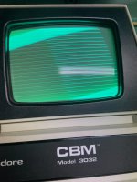
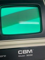
So, the slightly angled lines appear to be monitor flyback lines.

So either the video signal is not being blanked during the flyback time or the monitor brightness is too high (or the brightness control is not working correctly on the monitor).

The other thing I noticed is that the right hand edge of the monitor image (at the end of the lines) are not vertical.

Dave
 
Brightness is low and same problem when i swap the mainboard to the 3016 monitor. The 3016 mainboard is working on this monitor.
It's difficult to show it on the picture.
This one is better I think
3FA0BE4A-6F01-44E3-A279-91C484CC8E79.jpeg
 
Check the video signal arriving at the VDU connector at the input to the VDU's circuit with the scope, then as it passes through the transistor stages to the CRT cathode. The cathode voltage could be stuck low, in that case there is not nearly enough range in the brightness control to extinguish the CRT's beam and retrace lines will not be blanked either.
 
Well it's seems that the mainboard is working now. I switch again to the 3016 monitor and it's working. I was sure that i already did that, but i think i messed that up.
It's to hot to think right ;)

So the last picture is a problem with the monitor itself? i will first check the power supply.
 
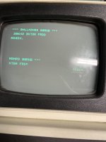
That looks like a stuck data line 0 at the video RAMs somewhere - or a stuck address line into the character generator originating from the video RAM D0.

The letter C is a B etc. with all the characters having D0 set to a '1' ending up one character 'lower' with bit D0 held low. Note that a D (which already has D0 low) is unaffected in the word COMMODORE.

That should give you somewhere to look.

Dave
 
Well it's seems that the mainboard is working now. I switch again to the 3016 monitor and it's working. I was sure that i already did that, but i think i messed that up.
It's to hot to think right ;)

So the last picture is a problem with the monitor itself? i will first check the power supply.
I cannot figure out, from what you are saying, where the problems might be, in the VDU or the computer board, and I don't know what "messed up means", or what precisely got messed up .
It is very confusing, making it hard to offer help.
What happened to the situation where the CRT beam current was too high and you could not turn the brightness down ?
 
Last edited:
As I undetstand it, the OP has been swapping things around to see which 'board' the problem resides on. I belive they have swapped the logic board and the monitor PCB on different occasions.

In one case I remember, when the logic board was swapped around, the fault moved with the board - ergo the logic board was at fault.

I think, in this case, that the OP was convinced the problem also stayed with the logic board but (on a subsequent test) this proved not to be the case.

This goes to demonstrate the value of keeping a logbook of your work (so that you can revisit what you have done in the past and what the results were) and to be clear and concise in your postings to us about what you have done, the results obtained, the conclusions you have drawn - and why.

Dave
 
This goes to demonstrate the value of keeping a logbook of your work (so that you can revisit what you have done in the past and what the results were) and to be clear and concise in your postings to us about what you have done, the results obtained, the conclusions you have drawn - and why.

Dave

That sounds a lot like Dr. Phil. "You cannot make sense out of nonsense".
 
Back
Top