• Please review our updated Terms and Rules here

COMMODORE CBM PET 2001-N DESPERATE

I am actually relieved both of them are bad! That is what I was hoping / expecting.

Does your IC tester inform you as to HOW they are faulty? I always find it useful to work out whether the fault(s) reported match the observed symptoms. I learn from this for the future...

>>> Next step?

Did you read post #363?

>>> When you have replaced I10 and I11, do NOT install the DRAMs - but leave our resistors in place.

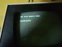
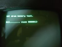
Test again with PETTESTER. Hopefully, this time we will observe the correct response we are looking for.

Please check that the resistor leads are installed correctly and are not shorting out to either each other or to anything else.

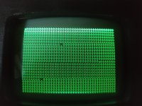
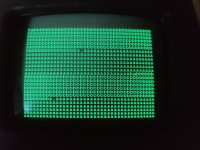
Post a photograph of the PETTESTER screen please.

Dave
 
Does your IC tester inform you as to HOW they are faulty? I always find it useful to work out whether the fault(s) reported match the observed symptoms. I learn from this for the future...
my logic tester tell me only "error" if IC is bad...
 
The screen is bad again 🥲
 

Attachments

  • 1735648661353525691321288729596.jpg
    1735648661353525691321288729596.jpg
    2 MB · Views: 6
That is EXACTLY what I was expecting!

With all of the resistors installed, the data lines of the (not inserted) DRAM are being held at a logic '0'.

The PETTESTER is, therefore, reading a constant $00 from the DRAM.

As a result, address $0000 is correctly reading a $00 (so is good) and all of the other addresses are still reading $00 (which are bad). This accounts for the single 'g' and all of the other 'b' characters.

Because the 'bad' memory addresses are reading $00, the display of the actual bad character read is '@' (the PETSCII character for $00).

In addition, pages 0 and 1 are now displaying identical contents (they were not previously).

Now, disconnect the resistor from pin 2 of I9. This should result in the data being read back from the 'DRAM' of $01.

Post a photograph of the screen and return the resistor back into pin 2 of I9. The screen display should return to that of post #383.

Note the position of the 'g' character and the load of characters displayed for the 'bad' memory addresses...

Dave
 
This is the problem. If you don't understand how PETTESTER is operating, and what the display is telling you about the fault, then all you are using the PETTESTER display for is a GO/NOGO indicator - just like your IC tester.

The difference is that PETTESTER is providing meaningful information about 'how' the tests are failing. However, in order to understand how this relates to the hardware itself, you have to have a knowledge about (in this case) how DRAM and 74LS244 buffers work and how the PET video sub-system uses these components to write to (and read from) the DRAM.

The operation of this test was explained in my answer to @ScottishColin in a previous post.

This means either you put some effort into studying the theory (and I am willing to help you here) or you will not progress further than random chip replacement.

To be quite clear, this will be the last PET that I am 'remotely' fault finding for you. This takes up too much of my time and is stuff that you should be learning how to apply in your own time.

Have you reinstalled the resistor leg back into I9 pin 2 and have you got the same display as in post #373?

If so, repeat the same procedure as before (remove the resistor from pin 2, check the display, reinsert the resistor back into pin 2) for the following ICs in the identified order:

I8, I7, I6, I5, I4, I3 and I2.

At each stage you should see a block of characters displayed as follows:

All resistors in, data value $00, character '@'.

I9 resistor out only, data value $01, character 'a'.

I8 resistor out only, data value $02, character 'b'.

I7 resistor out only, data value $04, character 'd'.

I6 resistor out only, data value $08, character 'h'.

I5 resistor out only, data value $10, character 'p'.

I4 resistor out only, data value $20, character '[blank space]'.

I3 resistor out only, data value $40, character '-'.

I2 resistor out only, data value $80, character inverse '@'.

Smart people will recognise the same data pattern and PETSCII characters as we used when removing the video RAM and using the resistors to test the character generator and beyond.

If the above is OK, remove the resistors from I2 through I9 and reinstall the 4116 DRAM (the right way around) and retest with PETTESTER.

We have only tested the read buffers of the 244. We could test the 244 write buffers, but let's not bother and go for broke on the assumption that the 244 devices you have fitted are fully functional.

Dave
 
Last edited:
It's up to you now. If you want to learn, that is fine. I am happy to teach you.

We constantly keep telling you to learn some theory and learn how to better use your test equipment.

The best way to learn is to learn on a PET that actually works!

Dave
 
This is the problem. If you don't understand how PETTESTER is operating, and what the display is telling you about the fault, then all you are using the PETTESTER display for is a GO/NOGO indicator - just like your IC tester.

The difference is that PETTESTER is providing meaningful information about 'how' the tests are failing. However, in order to understand how this relates to the hardware itself, you have to have a knowledge about (in this case) how DRAM and 74LS244 buffers work and how the PET video sub-system uses these components to write to (and read from) the DRAM.

The operation of this test was explained in my answer to @ScottishColin in a previous post.

This means either you put some effort into studying the theory (and I am willing to help you here) or you will not progress further than random chip replacement.

To be quite clear, this will be the last PET that I am 'remotely' fault finding for you. This takes up too much of my time and is stuff that you should be learning how to apply in your own time.

Have you reinstalled the resistor leg back into I9 pin 2 and have you got the same display as in post #373?

If so, repeat the same procedure as before (remove the resistor from pin 2, check the display, reinsert the resistor back into pin 2) for the following ICs in the identified order:

I8, I7, I6, I5, I4, I3 and I2.

At each stage you should see a block of characters displayed as follows:

All resistors in, data value $00, character '@'.

I9 resistor out only, data value $01, character 'a'.

I8 resistor out only, data value $02, character 'b'.

I7 resistor out only, data value $04, character 'd'.

I6 resistor out only, data value $08, character 'h'.

I5 resistor out only, data value $10, character 'p'.

I4 resistor out only, data value $20, character '[blank space]'.

I3 resistor out only, data value $40, character '-'.

I2 resistor out only, data value $80, character inverse '@'.

Smart people will recognise the same data pattern and PETSCII characters as we used when removing the video RAM and using the resistors to test the character generator and beyond.

If the above is OK, remove the resistors from I2 through I9 and reinstall the 4116 DRAM (the right way around) and retest with PETTESTER.

We have only tested the read buffers of the 244. We could test the 244 write buffers, but let's not bother and go for broke on the assumption that the 244 devices you have fitted are fully functional.

Dave
Tests are ok! Now i run the pettester
 
I am desperate!
 

Attachments

  • 17356596763257433524983591008796.jpg
    17356596763257433524983591008796.jpg
    1 MB · Views: 8
  • 17356597108062987732443405273155.jpg
    17356597108062987732443405273155.jpg
    1 MB · Views: 8
Let the f***ing RAM test work!

Most likely you have either a marginal video RAM chip or another bad IC socket pin connection.

We have (hopefully) fixed all of the faults now, bar a little problem with the video circuitry - and you suddenly get desperate!

Dave
 
What should the character be after the 16 (look in my PETTESTER manual). Then lookup the PETSCII code for that character.

Lookup the PETSCII code for the character that is being displayed.

Convert the two character codes into binary.

Look for the bit(s) that differ...

Dave
 
The '16' is on the top left hand side of the screen and indicates the amount of memory that the PETTESTER has detected by using a very simple poke and peek algorithm.

What character should be displayed after the 16 (or 32 in the case of a fully-loaded PET RAM)?

This is not a trick question (it is on page 13 of my PETTESTER manual)...

Dave
17 ??
 
Back
Top