daver2
10k Member
+1.
All of the signals should swing between approximately 0V and +5V.
Dave
All of the signals should swing between approximately 0V and +5V.
Dave
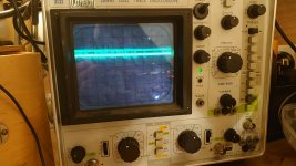
With the settings you suggest I get this for vertical.You are not making a recording of the vertical drive signal (if it is there ) yet, because in the three photos the scope timebase looks like its set on 20 uS/division.
To see the vertical pulses the timebase needs to be slowed right down because the spacing between the pulses is about 16.67 mS, so set the timebase for 5mS/division (or similar) when checking for the vertical pulses.
Make sure to have the scope's probe input on DC coupling (looks like it is), and set say for 2V/large division on the attenuator with a x1 probe, or if its a x10 probe set it for 0.2v/large division, which gives 2V/ large division with the x10 probe (a large division is usually a centimeter on the screen of most scopes). To be sure you have got that right, connect the probe onto the 5V supply and the trace should jump up by 2.5 large divisions = 5V.
Well I have been back tracking from the vertical signal and pin 3 of C7 is not outputting anything on the scope. Probe is lo on pin 3. It is getting a clock signal on pin 12 pulsing so I suspect it is that it is C7 74ls107 possibly causing the vertical loss.
For a few minutes I had a full screen of lines and mess now nothing again. No output from horizontal either. So I guess something else has failed.
B6IMHO Forget the scope! Get that logic probe going again!
So do you have pulses on J7 pin 5 now? If so the horizontal might be better.
For the vertical...
How about J7 pin 3?
How about pins 2,3 and 5,6 of B6?
You do need to be very methodical here otherwise it will go pear shaped.
OK... Again pin 2 and 3 being opposites and pin 5 and pin 6 being opposites is a good sign for the health of B6... but they should be changingB6
Pin 2 lo
Pin 3 hi
Pin 5 lo
Pin 6 hi
J7
Pin 3 Hi
Pin 5 lo
No pulse on any of these .
I was getting a good square wave on the horizontal after changing C9 with a white line on the screen and for a short while a full screen which came and went.

Thankyou for confirming my suspicions on C7.Replace 74LS107 at C7
Play with your scope whilst you wait for your parts to arrive
A trace of pin 12 of C7 would be nice and keep Hugo happy
Sorry... i've just changed my mind!Thankyou for confirming my suspicions on C7.
I ordered one earlier today.
I will try and get a picture of the scope reading of pin 12 before I extract it and post.
")