• Please review our updated Terms and Rules here

Commodore PET 2001-8 text wobbling on screen

The only "PET power supply" that is actually connected to the monitor PCB itself is an AC supply directly from the transformer - so no active or passive components at all... The rectification, smoothing and voltage regulation is all done on the monitor PCB. Yes, you can feed an external AC or DC supply into the monitor PCB itself.

Yes, you can separate the PET monitor from the PET case and extend the power and signal cables if you like. In fact, this is a good way of making sure that it is not magnetic interference from the transformer affecting the monitor image.

However, as Hugo has already stated, this can usually be done by viewing the monitor with the PET case closed and then open - as you have changed the distance and angle between the transformer and the CRT.

Can you post a video that I can actually view? I can't look at your previously posted videos (unfortunately). The office IT blocks them...

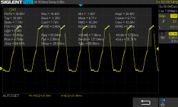
If you think it is power supply related - it is likely to be a component on the monitor PCB itself, and a simple probe with an oscilloscope should identify this. Set the timebase to view a 50/60 or 100/120 Hz signal and attach the oscilloscope probes to the DC voltage rail after the monitor voltage regulator.

I would also view the stability of the HDRIVE signal on the oscilloscope.

R20 is a cheap commodity item. If you have already removed it - and are having problems with it - replace it. Simple as that and then we can move on...

Dave
 
Basically, the AC supply arrives at the monitor PCB from the transformer.

Diodes CR19-CR22 are a full-wave bridge rectifier to convert the AC voltage into a DC voltage.

Capacitor C1 smooths the pulsed DC from the bridge rectifier and feeds the input to the 12V voltage regulator (VR1).

The 12V output from VR1 is smoothed via capacitor C3.

Basically, measure the DC voltage across first C1 and then C3.

We are looking to see any sign of 50/60/100/120 Hz ripple on both the input and output side of the VR1 12V voltage regulator.

EDIT: The Horizontal drive also takes the +12V rail and has a series resistor (R34 10 Ohms) and smoothing capacitor C17 all of its own. So it would be worth measuring the DC voltage across C17 - also looking for ripple.

Dave
 
hi Dave,
I have swapped R20 potentiometer and no change. I will look for other advices.thanks
 
Last edited:
I have measured DC voltage across C17. This is how it looks like. Is it normal?
IMG_4325.jpeg
 
I also did 3 tests to check magnetic interference dependency, because something was not clear to me. The results really confused me and surprised me.
  • Test 1 - I put monitor in its oryginal position (on PET case) ant turn power on. I was able to see whole text on the monitor wobbling a little.
  • Test 2 - I connected monitor outside PET case with longer cable adapter (0,5m) to further distance between monitor and power transformer. I was able to see only first line (****Commodore Basic****) wobbling a little. other lines weren't.
  • Test 3 - This is Test 2 scenario + I powered on bench DC power supply that was standing next to CRT (10 cm from the front of the monitor). I saw text wiggling on monitor too.

The question is, can we eliminate it somehow? Is this a result of one of the monitor PCB compenents that is likely sensitive and vurnelable for such interference and do such bad job?

When I turn on PET I can hear a litte humming sound from main transformer.
 
Have you done the same with C1 and C3 before we start delving inside the circuitry

A story has a beginning, a middle and and end.

C1 is the beginning, C3 is the middle and C17 is the end.

A small amount of transformer hum would be normal.

Dave
 
Some new measurements:
1.AC voltage across CR19,CR21 (before rectification):
SDS00008.png
2.DC voltage across CR19,CR21 (after rectification) and that goes to C1 (+):
SDS00009.png
3. DC voltage across C3 (after regulation from VR1):
SDS00011.png
 

Attachments

  • SDS00008.png
    SDS00008.png
    28.3 KB · Views: 1
1. I don't think the AC voltage measurement is correct. On the negative half cycle, the voltage only goes to -1.4V. I suspect this to be a measurement error issue with the oscilloscope probe ground clip. This clip will be connected to mains earth internally...

Using a multimeter set to AC Volts would be a much better way to measure this.

If you want to measure it with an oscilloscope, make sure the transformer winding is not connected to mains earth at either end, and measure the voltage on the oscilloscope with it NOT connected to the monitor.

2. Looks fine. You can see that one pair of diodes has a slightly lower voltage drop than the other pair - not that this is a problem of course.

3. Looks well fine.

Dave
 
Hi Dave,

AD. 1. You are right I connected ground probe clip to PCB ground.

Do you have any other ideas what to check? Is there any other suspicious component I need to check for this behavior? Thanks
 
I have asked for a video of the problem that I can view...

Post #9 had a 'wobble' on your external monitor using the RGBtoHDMI converter. This was 'fixed' by post #10.

Unfortunately, I can't view the video in post #12. My laptop and phone just wants to download the MOV file - not view it... Any chance of posting a little video elsewhere (YouTube?) so that I can see what your problem looks like on the PET monitor?

I also asked to see what the stability of the HDRIVE signal is like.

To do this, measure VDRIVE on one channel of your oscilloscope. Set this channel to be the trigger for the oscilloscope.

Measure HDRIVE using the second channel of your oscilloscope.

Adjust the oscilloscope timebase to see a number of HDRIVE pulses on the screen - and see how stable they are with respect to the VDRIVE signal.

If this HDRIVE signal is 'solid' wrt the VDRIVE signal - the problem must be in the monitor.

In this case, the interaction should either be power-supply related (ruled that out) or magnetic interference.

You stated that moving the monitor outside the casing did have an effect (post #26 test 2). This does imply magnetic coupling...

Your metal case (of the PET) is actually earthed to the mains earth isn't it?

I hate these types of problems :)...

Dave
 
Back
Top