daver2
10k Member
The only "PET power supply" that is actually connected to the monitor PCB itself is an AC supply directly from the transformer - so no active or passive components at all... The rectification, smoothing and voltage regulation is all done on the monitor PCB. Yes, you can feed an external AC or DC supply into the monitor PCB itself.
Yes, you can separate the PET monitor from the PET case and extend the power and signal cables if you like. In fact, this is a good way of making sure that it is not magnetic interference from the transformer affecting the monitor image.
However, as Hugo has already stated, this can usually be done by viewing the monitor with the PET case closed and then open - as you have changed the distance and angle between the transformer and the CRT.
Can you post a video that I can actually view? I can't look at your previously posted videos (unfortunately). The office IT blocks them...
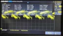
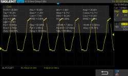
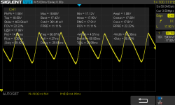
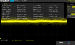
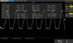
If you think it is power supply related - it is likely to be a component on the monitor PCB itself, and a simple probe with an oscilloscope should identify this. Set the timebase to view a 50/60 or 100/120 Hz signal and attach the oscilloscope probes to the DC voltage rail after the monitor voltage regulator.
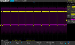
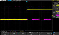
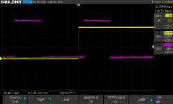
I would also view the stability of the HDRIVE signal on the oscilloscope.
R20 is a cheap commodity item. If you have already removed it - and are having problems with it - replace it. Simple as that and then we can move on...
Dave

