• Please review our updated Terms and Rules here

Commodore pet flickering screen

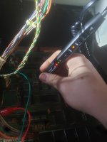
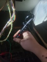
I agree with the logic probe suggestion.

If you have not owned a scope before, a very good place to start is with an analog scope. Not so vintage that it is unreliable and needs repairs though.

Hitachi made a very good range of reliable scopes, the compact ones are the V509, V209, but other models like the V212 turn up, often well cared for probable one owner types from estate sales, one typical example:


These sorts of scopes are intuitive, dead easy to use. Once you have mastered it in a few years you can move to digital scopes which can be a little more tricky to set up correctly, but have lots of additional features.

Once you start to use a scope, and can see into the dynamics of the circuits you are working with, building or repairing, whatever those circuits are, analog, digital etc, you will wonder how on Earth you ever managed without one, because it is a whole new world of understanding and insight.
 
Don't forget to add your location into your profile.

When the monitor displays the screenful of random characters - this indicates to me that the CPU is not functioning correctly either. However, it does indicate that the clock is working (otherwise you wouldn't have got the random characters displayed).

The first thing is to hop over to Bo's website at http://www.zimmers.net/anonftp/pub/cbm/schematics/computers/pet/2001/index.html and download the schematics related to your particular machine.

If your monitor is playing up, I would suggest disconnecting it for the time being to prevent further damage. You can do this via the plug and socket at the monitor PCB - not on the main logic board (the power is fed directly to the monitor from the transformer).

The second thing to do is to measure all of the DC voltage rails to ensure that they are within specification (+/-5% of nominal voltage). This would be between 4.75V and 5.25V for a +5V rail. However, I would expect it to be realistically between 4.9V and 5.1V.

I think (for your machine) there should be four (4) +5V voltage regulators - each providing a supply to part of the logic.

The next thing is to measure the ripple voltage - using a low voltage AC range on your multimeter. The ripple should be within +/- 0.1V.

Just a point of note, all measurements are taken relative to the 0V/GND rail.

After that, you need to really purchase a logic probe. These are quite cheap. Have a look at the "Laser 5263". This will work with TTL or CMOS devices and indicates logic HIGH, logic LOW and has a PULSE catching option. Ask Santa as Christmas is coming...

You can take some measurements around the CPU with your multimeter, but I can tell you how to do that after you have looked at the power rails.

You can also work on the monitor in parallel - by connecting it and disconnecting it. However, you are aware of the high voltages on the monitor I assume and how to work safely on a monitor? If not, please ask for further advice. Safety First! Also, I wouldn't operate the monitor for too long with the fault as at present.

Dave
I checked the power rails on the main board, all the regulators are in that sweet spot around 5v to 5.15v dc, and i got a logic probe coming in the mail. Should be here any minute its a cheap little lp-560, so hopefully that should help.

Santa is coming early lmao
 
Don't forget to add your location into your profile.

When the monitor displays the screenful of random characters - this indicates to me that the CPU is not functioning correctly either. However, it does indicate that the clock is working (otherwise you wouldn't have got the random characters displayed).

The first thing is to hop over to Bo's website at http://www.zimmers.net/anonftp/pub/cbm/schematics/computers/pet/2001/index.html and download the schematics related to your particular machine.

If your monitor is playing up, I would suggest disconnecting it for the time being to prevent further damage. You can do this via the plug and socket at the monitor PCB - not on the main logic board (the power is fed directly to the monitor from the transformer).

The second thing to do is to measure all of the DC voltage rails to ensure that they are within specification (+/-5% of nominal voltage). This would be between 4.75V and 5.25V for a +5V rail. However, I would expect it to be realistically between 4.9V and 5.1V.

I think (for your machine) there should be four (4) +5V voltage regulators - each providing a supply to part of the logic.

The next thing is to measure the ripple voltage - using a low voltage AC range on your multimeter. The ripple should be within +/- 0.1V.

Just a point of note, all measurements are taken relative to the 0V/GND rail.

After that, you need to really purchase a logic probe. These are quite cheap. Have a look at the "Laser 5263". This will work with TTL or CMOS devices and indicates logic HIGH, logic LOW and has a PULSE catching option. Ask Santa as Christmas is coming...

You can take some measurements around the CPU with your multimeter, but I can tell you how to do that after you have looked at the power rails.

You can also work on the monitor in parallel - by connecting it and disconnecting it. However, you are aware of the high voltages on the monitor I assume and how to work safely on a monitor? If not, please ask for further advice. Safety First! Also, I wouldn't operate the monitor for too long with the fault as at present.

Dave
I have gotten my logic probe in, and I've checked all the 5v regulators, and they seem to be functioning correctly.
 
So, ready to rock and role then!

All of these measurements are on the 6502 CPU:

You will need to clip your logic probe on to a source of +5V and set the switch to TTL.

Let's see what you make of the logic states just using your HIGH and LOW (read and green LEDs) to start with. And then we will move on to the YELLOW LED...

Pin 2 (RDY) should be HIGH.
Pin 4 (/IRQ) should be HIGH or PULSING - not permanently LOW.
Pin 6 (/NMI) should be HIGH.
Pin 7 (SYNC) should be PULSING (assuming the CPU is expecting instructions). It will be LOW otherwise.

Pin 39 should have a 1 MHz clock on it. Your logic probe may not be able to resolve this though. It may be way too fast for it.

Pin 40 (/RESET) should start off LOW when you first power the PET on. It should stay LOW for a while (approximately 1 second ish) and then go HIGH.

Dave
 
The connector on the video board is notorious for intermittent contact, as is the main power connector on the PET pcb and all the IC sockets.
 
So, ready to rock and role then!

All of these measurements are on the 6502 CPU:

You will need to clip your logic probe on to a source of +5V and set the switch to TTL.

Let's see what you make of the logic states just using your HIGH and LOW (read and green LEDs) to start with. And then we will move on to the YELLOW LED...

Pin 2 (RDY) should be HIGH.
Pin 4 (/IRQ) should be HIGH or PULSING - not permanently LOW.
Pin 6 (/NMI) should be HIGH.
Pin 7 (SYNC) should be PULSING (assuming the CPU is expecting instructions). It will be LOW otherwise.

Pin 39 should have a 1 MHz clock on it. Your logic probe may not be able to resolve this though. It may be way too fast for it.

Pin 40 (/RESET) should start off LOW when you first power the PET on. It should stay LOW for a while (approximately 1 second ish) and then go HIGH.

Dave
So after going around the 6502, the picture below is what i found.

But while probing around, i found that the horizontal line will go from data (when the screen is functioning perfectly), to high, causing the screen to turn off, (on the main board). When it stops being high the screen goes back to normal. Any idea on what could cause that?
 

Attachments

  • 20221218_144143.jpg
    20221218_144143.jpg
    3.1 MB · Views: 6
  • 20221218_150435.jpg
    20221218_150435.jpg
    1.3 MB · Views: 6
  • 20221218_150627.jpg
    20221218_150627.jpg
    1.7 MB · Views: 6
So, ready to rock and role then!

All of these measurements are on the 6502 CPU:

You will need to clip your logic probe on to a source of +5V and set the switch to TTL.

Let's see what you make of the logic states just using your HIGH and LOW (read and green LEDs) to start with. And then we will move on to the YELLOW LED...

Pin 2 (RDY) should be HIGH.
Pin 4 (/IRQ) should be HIGH or PULSING - not permanently LOW.
Pin 6 (/NMI) should be HIGH.
Pin 7 (SYNC) should be PULSING (assuming the CPU is expecting instructions). It will be LOW otherwise.

Pin 39 should have a 1 MHz clock on it. Your logic probe may not be able to resolve this though. It may be way too fast for it.

Pin 40 (/RESET) should start off LOW when you first power the PET on. It should stay LOW for a while (approximately 1 second ish) and then go HIGH.

Dave
Even while the monitor is completely unplugged from the main board, the horizontal line is still going high on its own, so I've isolated the problem to the main board
 
Even while the monitor is completely unplugged from the main board, the horizontal line is still going high on its own, so I've isolated the problem to the main board
Good work.

When you say "horizontal line" are you are meaning the H.drive signal from the computer board ?

If that is stopping, going High or Low , it would certainly cause the VDU to cut out. The VDU relies on it to power the CRT and H scan circuits.

One thing to check would be the V.drive signal too, to find out if that is cutting out at the same time, indicating a problem somewhere early on in the clock circuits & counters, or if it is just the H.drive signal on its own that goes abnormal.
The label on the connector, (the video cable going from the main board to the monitor board a.k.a. j7) lables the line as "hor 3".

And yeah, the verticle line, (ver 3) also changes from high pulsing to low pulsing when the screen cuts out.
And the video pulse (vid 1 on j7) also goes from high-low-pulsing, to just high

What could that be?
Could the 6522 via be bad? If so i have 2 out of a vic-20 that I could pillage.
 
Last edited:
That is excellent deductive work, and a major 'hit' for your new piece of test equipment.

The CPU appears to be running something (pin 7 is ticking away niceley.

Let me have a look at the schematics and a think regarding your monitor drive issue.

Dave
 
That is excellent deductive work, and a major 'hit' for your new piece of test equipment.

The CPU appears to be running something (pin 7 is ticking away niceley.

Let me have a look at the schematics and a think regarding your monitor drive issue.

Dave
Im not sure if this helps, but i have this revision of the motherboard
 

Attachments

  • PET2001BoardLabeled.jpg
    PET2001BoardLabeled.jpg
    1 MB · Views: 7
Can you use your logic probe and check the following two pins please:

C7/3.
C5/12.

I suspect a clock is erratic somewhere.

We are looking for odd behaviour (as you saw on the H.DRIVE and V.DRIVE signals).

Dave
 
Can you use your logic probe and check the following two pins please:

C7/3.
C5/12.

I suspect a clock is erratic somewhere.

We are looking for odd behaviour (as you saw on the H.DRIVE and V.DRIVE signals).

Dave
(For when the screen cuts out or blanks)
C5/12- no change
C7/3- from low-pulsing to just low

For C9 is there a specific pin i should monitor?
 
What pin should i check
I'm not sure I'm looking at the exact schematic for your computer, if we could post the exact one so we are all on the same page to be sure.

The best move when you come to testing an IC is to look up its data sheet:


(unfortunately there is a 74LS93A with an altered pin out so avoid that one)

You will see it has four flip flops in it, an isolated one clock pulse Cp0 on pin 14 and Q0 output on pin 12

Then there are three flip flops in a chain, clock pulse Cp1 on pin 1 and outputs Q1,Q2,Q3 on pins 9, 8 and 11 respectively.

So the pulses on pin 9, would represent the divided clock on pin 1 by a factor of 2, that on pin 8 a divide by 4 and that on pin 11 a divide by 8 of the clock pulse on pin 1.

In the circuit they use the pin 8 and pin 11 outputs, so check those for pulses, if they are disappearing then check the clock pulse on pin 1. If that is present when the output disappears, it could be a faulty 74LS93, but it also pays to check the reset pins , 2 & 3 that they are not being deployed. THe IC could be ok and its clock pulse on pin 1 going awol.
C9/1- No change (high-Low-pulsing)
C9/2- No change (low)
C9/3- No Change (low)
C9/8 No change (high-low-pulsing)
C9/11 No change (high-low-pulsing)
 
Last edited:
OK, so when you say "no change" you mean that the fault comes & goes and there is no change on any of these pins ? That means that the IC is likely ok and that the fault is occurring in the circuit chain downstream after this IC.

But to be sure, check the other flip flop in there, pin 14 and 12.
 
OK, so when you say "no change" you mean that the fault comes & goes and there is no change on any of these pins ? That means that the IC is likely ok and that the fault is occurring in the circuit chain downstream after this IC.

But to be sure, check the other flip flop in there, pin 14 and 12.
No change in those pins either, but i did some probing around and i found some others

D5/11- high-low-pulsing to low
D6/12- high-low-pulsing to low
C7/2- high-pulsing to high
C2/1- high-low-pulsing to high
C3/1- high-low-pulsing to low
C4/1- high-low-pulsing low
C5/1- high-low-pulsing to low
 
Ok, I'll need to look at the schematic on a large screen and not my phone!

How good is your digital logic theory?

Can you follow simple AND, OR, NAND, NOR and INVERTER logic?

What about flip flops?

Hugo, we are working on this schematic I think: http://www.zimmers.net/anonftp/pub/cbm/schematics/computers/pet/2001/320008-3.gif.

Basically, all of the timing starts with an 8 MHz crystal oscillator and is then divided down by flip flops and gated to produce the correct pulses. Each logic gate should operate as per a simple truth table. One IC package or gate somewhere isn't.

We have to find which gate is not working as per its specification by using the data sheets, the test equipment available to us and our brains. It is a logic puzzle...

It is made a little more complex than that though because an output can (and does) get fed back to the input of a small part of the circuit.

We start out by assuming there is one fault that should solve all our observed problems, but keep in the back of our minds that we may have more than one concurrent fault to trip us up!

Dave
 
Last edited:
Back
Top