• Please review our updated Terms and Rules here

Cromemco dazzler replica project

Or not.. yikes! the switches alone would cost almost $200! Unless there are some cheaper alternatives out there?

Hi,

I buy switches for much less than that! Check JameCo for ON-ON swtiches, check eBay for switches ...

https://www.jameco.com/z/100SP1T1B1...T-ON-ON-120VAC-5A-1-4-Mount-MTS102_26332.html

The front panel doesn't need to look like an original, it just needs to make the computer functional. I've been exploring cheap to build wood cabinets of various designs for 8080 CPUs and Z-80 CPUs

1710351286352.png
 
Hi,

I buy switches for much less than that! Check JameCo for ON-ON swtiches, check eBay for switches ...

https://www.jameco.com/z/100SP1T1B1...T-ON-ON-120VAC-5A-1-4-Mount-MTS102_26332.html

The front panel doesn't need to look like an original, it just needs to make the computer functional. I've been exploring cheap to build wood cabinets of various designs for 8080 CPUs and Z-80 CPUs

Nice

I used the cheap ten for ~$3 Aliexpress ON-ON and ON-(ON) switches and a PCB dress panel for my SBC6120 front panel project and they worked fine.

 
The first command in the test program (converted to an RDOS command) is:
O 80 0E
This turns ON the Dazzler and sets the base memory address to 0000.
The equivalent of the sense switch code (converted to an RDOS command) is:
O nn 0F
Where nn is the hexadecimal representation of the desired sense switch setting(s).
Dave, thanks - just having a little trouble getting started - when you say this O 80 0E is the (hex conversion) of the first command - which particular test # were you looking at in the manual? I'd like to be able to understand what you did so I can covert the rest myself, I'm just not sure where you started! Thanks :)
 
If you look back at my post in #358 you will observe the initial part of my program as:

Address: Data
0000: 076
0001: 200
0002: 323
0003: 016

My mind doesn't think in OCTAL for a Z80, so I will convert it to HEXADECIMAL:

0000: 3E
0001: 80
0002: D3
0003: 0E

Even this is still not readable by a human, so I will lookup the hex codes for each instruction and turn it back into assembler.

0000: LD A,80h
0002: OUT (0Eh),A

This program loads the hex value of 80h into the accumulator (A). It then outputs the value in the accumulator (A) to I/O port 0Eh (the dazzler).

This can be directly implemented by the RDOS command: O 80 0E.

This command outputs the value 80 (hex) to I/O port 0E.

80 (hex) is 1000 0000 in binary.

Look at the I/O port assignments for the dazzler - in particular port 0Eh.

The most significant bit being set causes the dazzler to be enabled (turned on).

The remaining bits (all zero) are loaded into the latches that become A15..A9 of the dazzler's DMA (Direct Memory Access) for accessing the memory for the graphical image. By loading zeros into this register, this means that the starting address for the dazzler's memory base is 0000h.

This is not a specific test in itself, but part of the initialisation of the dazzler.

Is what I have explained here understandable?

If not, I will explain it in more detail for you.

Dave
 
I assume you have a Rev. C board set. Is that correct?

Have you installed all of the links (as per the assembly instructions)?

Board 1: SYNC IN to GND.

Board 2: J1 to J7 to correctly address the dazzler card at I/O ports 0Eh and 0Fh.

You also realise that the Dazzler card is normally switched OFF and will only display a picture when you set bit 7 of I/O port 0Eh (e.g. RDOS command "O 80 0E").

Just want to cover the "obvious" things...

Dave
 
Looking back at your PCB photographs, I see you have a Rev. D board.

My comments in #367 are still applicable however.

Looking back at an earlier post (#340) you state:

>>> R1 says 80k, should be 30k.

R1 should be 270 Ohms.

Dave
 
Looking back at your PCB photographs, I see you have a Rev. D board.

My comments in #367 are still applicable however.

Looking back at an earlier post (#340) you state:

>>> R1 says 80k, should be 30k.

R1 should be 270 Ohms.

Dave
He has a board created from Hugo's traces which were Rev C
 
OK...

I had better check the Rev. C schematics for the value of R1...

Yes, on the Rev. C board, R1 is still 270 Ohms.

Dave
 
Last edited:
Looking back at your PCB photographs, I see you have a Rev. D board.

My comments in #367 are still applicable however.

Looking back at an earlier post (#340) you state:

>>> R1 says 80k, should be 30k.

R1 should be 270 Ohms.

Dave
Correct. R1 is 270 ohms on both RevC and RevD boards.

There is a typo in post 340 - the reference to "R1 should be 30K" should have said "R11 should be 30K".
 
Im sorry if this has been covered but what are you all doing for the heatsink and plastic tabs to make your boards look like the originals?
 
If you mean the card extractors, it seems that Chromemco shipped the kits/boards without the extractors. At least they are not part of the BOM. But I guess white ones were most common at the time with S-100 boards (e.g. DigiKey part # 492-1024-ND).

Concerning the heat sinks, there are several manufacturers producing that style of heatsink, but the only one I found which is still available is Assmann V5234B-T.

-Ansgar
 
I assume you have a Rev. C board set. Is that correct?

Have you installed all of the links (as per the assembly instructions)?

Board 1: SYNC IN to GND.

Board 2: J1 to J7 to correctly address the dazzler card at I/O ports 0Eh and 0Fh.


Dave

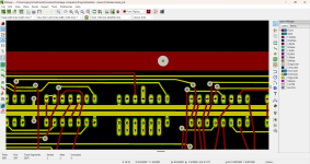
cant see the jumpers on board 2 ?

If its the extended pads at IC45, I cant see how they work ? They dont jumpe from anywhere to anywhere ?

1710616217771.png
 
Last edited:
I assume you have a Rev. C board set. Is that correct?
I have a Rev. C board set, but I have made the Rev. D mods

Have you installed all of the links (as per the assembly instructions)?

Board 1: SYNC IN to GND.
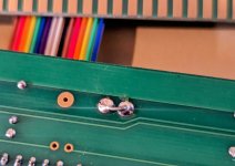
Yes I did add a jumper between IN and GND:
PXL_20240316_185313046.MP~2.jpg

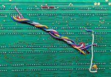
Board 2: J1 to J7 to correctly address the dazzler card at I/O ports 0Eh and 0Fh.
In this picture you can see I have jumpered J1-J7 (though not as pretty of a job as Hugo's!) - I need to double-check this work (EDIT: just went through and confirmed my jumper wires are correct). In this photo you can also see the REV D mods (adding cap & resistor) - Could someone confirm I did this correctly? (EDIT: still not certain in these mods) The red wire mods at the top of the board were to fix the couple of missing traces.
PXL_20240316_185605071~2.jpg

You also realise that the Dazzler card is normally switched OFF and will only display a picture when you set bit 7 of I/O port 0Eh (e.g. RDOS command "O 80 0E").
I have tried the KSCOPE and GDEMO applications, am incorrectly assuming that these application would be sending the init/ON commands?

Looking back at an earlier post (#340) you state:

>>> R1 says 80k, should be 30k.
Sorry if I wrote R1, it should have been R11! My mistake in post #340 & thanks for catching it. R11 is labeled as 80k, but should be 30k. R1 is correct.
 
Last edited:
cant see the jumpers on board 2 ?

If its the extended pads at IC45, I cant see how they work ? They dont jumpe from anywhere to anywhere ?

According to the Assembly Instructions in the manual, you have to solder in jumper wires to complete this step.
1710616801579.png
 
This can be changed by using the RDOS 'K 0F00' command to move the default stack and data area outside of the Dazzler screen address starting at address 0000. You can poke addresses 0000 upwards to your heart's content then without crashing the machine!

Unfortunately the "K" command isn't working for me. I have a 16FDC/RDOS 2.52 - I don't see this command in the manual. I think this was a command from the 4FDC version but I don't see an equivalent.

I tried issuing "O 80 0E" but I don't see so much as a flicker on the screen. I know that alone won't display anything but I was hoping to at least see some sign of life.
 
Im sorry if this has been covered but what are you all doing for the heatsink and plastic tabs to make your boards look like the originals?

Hi,

No reason to try and make it look exactly like the originals since these are reproductions. Function is the key, looks are for saving money on components.


.
 
Hi,

No reason to try and make it look exactly like the originals since these are reproductions. Function is the key, looks are for saving money on components.


.
I know, Im only building one for my Cromemco CS-1, I am not going to sell it. But Id like it to at least look like the other boards in the system ya know?
 
Back
Top