• Please review our updated Terms and Rules here

Dead 2001

With the character generator out of the socket - we can fully test the parallel to serial shift register (B2) and subsequent logic by 'hard wiring' the data output pins of the (now removed) character generator ROM socket to +5V and 0V (via low-valued resistors). This should give you different vertical lines, one line for each data bit pulled high...

You would also be advised to carry on with your scoping of the various counters etc. to see if anything else is clearly amiss. For example, the outputs from A1 should be clocking away happily. These three bits to the character ROM address the individual vertical lines of the character formation.

Dave
 
I noticed that, with power cycles, especially from cold, the screen will switch from vertical to horizontal bars, even giving a flickering between them. But it settles on the horisontal bars.
.
(Note, this is with the HDMI converter, will try and also test with an analog converter, just to make sure the HDMI converter is not introducing new complication - but don't think so.)
.
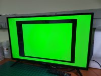
When I remove the Char ROM, I get a solid screen as per below.

2001-Video-06 - no char rom.jpg
 
OK, so the parallel to shift register (B2) is probably OK - but we haven't tested out the possibly 'stuck bit'.

I would not do to many power cycles with a fledging PET we are bringing back from the dead - you will kill more stuff...

You can fit a manual reset pushbutton by soldering it across capacitor C6 (0.1 uF) - close to the NE555 reset circuit.

I suspect that the constant power cycles are just causing some chips to initialise to semi-random values - especially on the video side (as opposed to the synchronisation side). We need to do some more debugging with the oscilloscope and our grey matter...

Dave
 
With the character generator out of the socket - we can fully test the parallel to serial shift register (B2) and subsequent logic by 'hard wiring' the data output pins of the (now removed) character generator ROM socket to +5V and 0V (via low-valued resistors). This should give you different vertical lines, one line for each data bit pulled high...

You would also be advised to carry on with your scoping of the various counters etc. to see if anything else is clearly amiss. For example, the outputs from A1 should be clocking away happily. These three bits to the character ROM address the individual vertical lines of the character formation.

Dave
OK, that sounds like a plan. Let me do that and revert.
.
Unfortunately I had to step away for now but will get back to it during the week.
.
In the mean time, any hints on how to read the relevant portions of the circuit will be great. While I can't get to the workshop (work, it's a bitch :(), I can comfortably work through the schematic while in boring meetings! :LOL: And learning the circuits is the really cool bit about fixing these guys. 😍
 
Unfortunately, I am on a business trip for a couple of days.

I will be able to check progress in the evening via my phone. It is not too easy to check schematics etc. via a phone though.

Perhaps we can reconvene later in the week.

Yes, if it wasn't for work I would be able to do much more with my hobby - but not have the money to buy expensive bits of kit!

Dave
 
Quick update, only had an hour this morning to further look at the video circuit. From what I can could see everything around the RAM and ROM works fine, the latches, etc.
.
RAM address lines were all active, /WE stayed high, however the databus from the video RAM was static on EE. PETSCII Char 239 is a horisontal bar but not 238, but I'm not sure if I'm reading the table correctly or if I'm out by 1.
.
But I was pretty confident that the SRAM is faulty, so decided to replace them both.
.
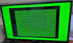
When I pulled the old chips and before plugging new ones in, I got a checker board pattern which was quite promising.

2001-Video-07 - no video ram.jpg

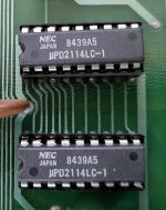
Then added NOS 2114s from 1984 :)

2001-Video RAM.jpg


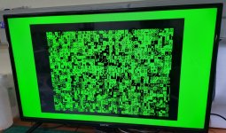
And, voila!! Getting the expected random characters screen. :)

2001-Video-08.jpg

Happy that the video circuit side of things are now working. Now on to fixing the actual computer. :)

I did quickly plug in a RAM/ROM replacement board but no joy. Fully expected this. Will be out of town till Monday but will then begin on that side.
 
Good choice on the 1984 vintage Japanese made 2114 chips !

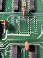
It also looks like you did a nice job removing the old IC's and fitting the sockets, or the sockets may have been there from the factory.
 
It is good to see a pcb treated with the respect it deserves.

I think it is worth socketing the video RAM on most PETS, because the incidence of video RAM failure is very high and it eliminates the vagaries of the failure modes in these chips. And, as I mentioned, it is not like the main RAM array, where there are a lot of chips and in the case they are soldered in, there are various diagnostic methods to hone in on the defective IC's and global replacement of those, unless in sockets already, is not sensible.
 
Since I'll be away from my workshop, for a few days, I might as well do some reading.
.
Are there any good guides / service manuals / circuit descriptions that give a (nice and friendly! :)) technical overview of the PETs, both non-CRTC and CRTC designs? I've not run into any in my searching, but then my Googling skills are as good as my skills at finding the Ketchup in the fridge.........
 
Most of what there is has been put together by the enthusiasts I am afraid.

Dave
It's quite sad how much knowledge is generated but not retained and eventually lost. Often permanently. And most of us, including myself, are guilty of this. We learn something, especially in a niche subject, but never go to the effort to preserve that knowledge for others who will need it.

@Hugo Holden 's articles on the PET CRT and Pong are great examples of how it could/should be done but also highlights the effort to do so.

Wonder if a Wiki-style, crowd sourced setup could work where people could contribute micro-bits of knowledge in an edited structure.
 
I have been restoring vintage equipment since the 1970's. The stuff I was working with back then included things like pre-WW2 radios & TV sets, mainly tube based gear, including audio amplifiers etc. Mostly I kept notes on these things in a filing cabinet.

As the years went by, and I went back to some of it, I realized that I should have better documented what I did. It is amazing when 20 years passes when you go back to something, you think...What did I do there and why? (I'm sure people who write a lot of code and don't comment it have the same dilemma).

I decided to make a website that was a not for profit idea, merely a repository for .pdf files.

Then, every time I did a restoration project, I would document it. That way anytime in the future I could go there and see what I did. But also it would be a link I could post to help others working with the same problems and vintage machines.

And you are right, it takes work and effort. It is much easier to fault find, repair and restore vintage systems without taking the time to write it up. Interestingly though, it is worth taking the time, because it will benefit yourself and many others.

One article I wrote about 10 years ago attracted a lot of attention. It was how to replace the Dallas BBNVSRAMs in TEk scopes like the 2465B with Ramtron FRAM. As the years went by I started getting emails from all around the world. From Universities and Tech Institutes, wanting to keep their scopes running and thanking me for the work.

So if you come across some problem in anything you are working on, especially if it looks like the kind of thing that will crop up in similar vintage units, the responsible thing to do is to document it and put it on a website, to help others who will run across the same problem.
 
Agreed 100%.
I keep thinking I'm going to do this, but usually don't find the time to publish anything. I'm no expert, but I'm sure those who are must have so much knowledge buried in their heads they should pass on to the community.
 
index.php

Anyone else worried about how very very small a finger Jannie has !

;)
 
Back at home and can now look at this again.

First order of the day was to replace the CPU socket. It was in a bad state and when I desoldered it, the solder sucker literally sucked some of the pins out the bottom of the board, basically they must've been rusted off between the board and the socket. I also pulled out the 3 IO chips.
.
Question: Will the machine boot with the 6520 / 6522 IO chips removed (assuming everything else is OK)? For example with a RAM/ROM replacement board in place?
 
Back
Top