• Please review our updated Terms and Rules here

Dead 2001

Jannie

Experienced Member
Joined
Feb 5, 2017
Messages
273
Location
Cape Town
Hey everyone!

Chicklet 2001's are super rare in my neck of the woods (South Africa) and, after many years of searching, I eventually found one. :)

I've repaired many a vintage computer, including a bunch of 8032s (with the help and guidance of the two Daves, and the likes of Mr. Holden, on this forum), but have never worked on a 2001. So hoping for a few tips and best practices to quickly point me where to start. I've read a number of threads, on this forum on similar repairs, such as this one. I'm relatively OK reading circuits and using test kit.

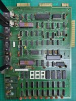
The board is marked as both a 320137 and 320136E and is a 2114 board. There are only 4 ROMs on the board.

The whole system have a huge amount of rust and a number of pins on the ROMs have rusted off. The Character ROM seems fine though and I can verify it in my EPROM reader.

Voltages (all 4), clock and reset are all good.

My understanding is that the 2001 should put out video signals, independent of the CPU side working properly. I'm not seeing this. H, V and Video show DC levels, so I thought I'd first start here.

Some questions, please:

- Is this correct? Can I assume that the video circuit should work independently of the "CPU" and I should get that working first? At least getting H- and V-sync signals before worrying about the CPU-side of things? (I did put in a RAM/ROM replacement board for a quick test but it did not make a difference).

- If so, are there a couple of obvious places to start / test? I've not yet done any tracing down the H/V sync paths.

- The IO chips look worse for wear, are they needed for the video circuit (like on the 8032) or can I safely ignore them / remove them from the board?

- Is there a service / repair manual for the 2001? I've searched quite a bit, but could not find one.....

Any help / tips / best practices / etc. will be really cool.

PET2001-01.jpgPET2001-02.jpg
 
Hello again!

That board doesn't look too bad (compared to some 'basket cases' we have seen!).

Usual place for schematics, manuals etc: http://www.zimmers.net/anonftp/pub/cbm/schematics/computers/pet/2001/index.html.

For your machine (2114 RAMs, 2316B ROMs and part 320137) is here: http://www.zimmers.net/anonftp/pub/cbm/schematics/computers/pet/2001/320137.pdf

What part numbers are on your ROMs?

You are correct. With the 2001 even removing the 6502 CPU doesn't stop the video from working!

The video circuit is on sheet 3 of the schematic. The trick is to start at the crystal oscillator and follow the clock signal through the flip flops. There is a problem because you end up at a couple of 'state machines' where the output is fed back to the input of the machine. This can get you (and us) confused as the state machine may have stopped working, but it is not necessarily easy to see the cause and effect...

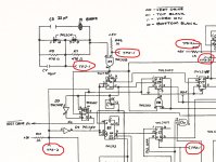
I would first start at C9 and (with your oscilloscope) see if you have a clock signal on pins 1, 8, 11, 14 and 12.

Dave
 
Last edited:
Hello again!

That board doesn't look too bad (compared to some 'basket cases' we have seen!).

Usual place for schematics, manuals etc: http://www.zimmers.net/anonftp/pub/cbm/schematics/computers/pet/2001/index.html.

For your machine (2114 RAMs, 2316B ROMs and part 320137) is here: http://www.zimmers.net/anonftp/pub/cbm/schematics/computers/pet/2001/320137.pdf

What part numbers are on your ROMs?

You are correct. With the 2001 even removing the 6502 CPU doesn't stop the video from working!

The video circuit is on sheet 3 of the schematic. The trick is to start at the crystal oscillator and follow the clock signal through the flip flops. There is a problem because you end up at a couple of 'state machines' where the output is fed back to the input of the machine. This can get you (and us) confused as the state machine may have stopped working, but it is not necessarily easy to see the cause and effect...

I would first start at C9 and (with your oscilloscope) see if you have a clock signal on pins 1, 8, 11, 14 and 12.

Dave
Thanks Dave!

I got the schematics from Bo's site, as per your link. It does seem the ROMs are not exactly the same but, I think, it's that CS high/low story and thus I have fewer (but bigger) ROMs.

I've not started tracing the sync signals, wanted to first confirm it makes sense. Will start doing that, first thing tomorrow, and post results. I had a quick look at the circuit and realised that there is some 'positive feedback' stuf happening that can really mess with you trying to fault find :)

Would my first priority be to get the sync signals working?

ROMs are as follows:

BASIC: 902465-01 / 02 (4KB each)
EDIT: 901447-24 (2KB)
KERNAL: 901465-03 (4KB)
CHAR: 901447-08 (2KB)

Wit the ROMs missing a number of pins (rusted off), I've removed them for now.
 
Last edited:
>>> Would my first priority be to get the sync signals working?

Sure would. Your starter for ten is in post #2 with device C9. Let's just work slowly through the logic one IC at a time and tick them off in order.

Dave
 
>>> Would my first priority be to get the sync signals working?

Sure would. Your starter for ten is in post #2 with device C9. Let's just work slowly through the logic one IC at a time and tick them off in order.

Dave
Coolios,

Seems like C9 is a prime suspect from previous threads as well. Will give it the 3rd degree! :)
 
I think you should be able to resurrect this board. It looks like it will clean up well. The rust can be cleaned off the ceramic gold top IC's with 1000 grade paper. Then apply Fertan rust converter, this will deactivate the rust in the pits in the metal. Then you could spray over that (obviously with masking) with a fine metallic Gold spray (Dupli-color make a good one) to restore the original appearance. If you spray over it without the Fertan, the rust will return and bubble up the paint. You can also use the Fertan on the rusty PET cabinet metalwork prior to the re-paint.

Where the IC pin rust has not destroyed the pin completely on the black bodied plastic ICs, you can clean that of with 1000 paper. If you fold it into a double thickness strip and form it into a shallow U curve, to make what amounts to a hand burnishing tool, that does not catch on adjacent pin edges when you run it across the pin surfaces. Then use contact cleaner. After the rust & oxidation is cleaned off, coat the pins in Inox's mx-3.

The original gold plated pins on those purple ceramic IC's tend to be very brittle and break off easily, so with those only very gentle minimal cleaning, only if they need it, and trying not to bend them at all.

It always amazes me the number of different versions of PET boards that there are. When I bought my PET I had no idea. When I opened it up it was a Dynamic PET with the 4116 DRAM.

I often wondered if SRAM might have been a better idea as it doesn't require all the additional IC's in the DRAM support circuitry. I like the 2114 . If you need some, there are some super good quality ones out there made by Intel the D2114 and very good ones from AMD too, the 9114 like these, the lovely ceramic case version is at Halbleiter where I get most of my vintage IC's . All of their stock are genuine vintage parts for the 70's & 80's and you never run into trouble with fake parts:


You will find that some are available as pulls, but with those you never really know what they have been subject to in the past. There are plenty of NOS 2114's on ebay to choose from though.

There is also a good 2114 tester on ebay from:

 
Last edited:
I think you should be able to resurrect this board. It looks like it will clean up well. The rust can be cleaned off the ceramic gold top IC's with 1000 grade paper. Then apply Fertan rust converter, this will deactivate the rust in the pits in the metal. Then you could spray over that (obviously with masking) with a fine metallic Gold spray (Dupli-color make a good one) to restore the original appearance. If you spray over it without the Fertan, the rust will return and bubble up the paint. You can also use the Fertan on the rusty PET cabinet metalwork prior to the re-paint.

Where the IC pin rust has not destroyed the pin completely on the black bodied plastic ICs, you can clean that of with 1000 paper. If you fold it into a double thickness strip and form it into a shallow U curve, to make what amounts to a hand burnishing tool, that does not catch on adjacent pin edges when you run it across the pin surfaces. Then use contact cleaner. After the rust & oxidation is cleaned off, coat the pins in Inox's mx-3.

The original gold plated pins on those purple ceramic IC's tend to be very brittle and break off easily, so with those only very gentle minimal cleaning, only if they need it, and trying not to bend them at all.

It always amazes me the number of different versions of PET boards that there are. When I bought my PET I had no idea. When I opened it up it was a Dynamic PET with the 4116 DRAM.

I often wondered if SRAM might have been a better idea as it doesn't require all the additional IC's in the DRAM support circuitry. I like the 2114 . If you need some, there are some super good quality ones out there made by Intel the D2114 and very good ones from AMD too, the 9114 like these, the lovely ceramic case version is at Halbleiter where I get most of my vintage IC's . All of their stock are genuine vintage parts for the 70's & 80's and you never run into trouble with fake parts:


You will find that some are available as pulls, but with those you never really know what they have been subject to in the past. There are plenty of NOS 2114's on ebay to choose from though.

There is also a good 2114 tester on ebay from:

Thanks for all the tips, Hugo! Especially on sources for legit replacements. I fortunately have some NOS 2114s but will need to order some more chips soon and the whole fake chip environment is quite stressful and shipping to ZA can be a real challenge.

I built one of Stephan Slabihound's excellent Retro Chip Testers a few years ago and it's been a life saver. It's crazy what this thing can test and it can also program some of the older EPROMs now as well.

I also think this machine will restore nicely. The board itself is in good condition. In the pic above, I just gave it a quick clean and will clean it properly once working. The case will need proper repainting.

What is the general view on sockets, especially the white ones? Replace outright? And, if replacing, what's the safest method to protect the board? Can the white plastic be pulled off the pins, so one could desolder the pins one by one, or must I desolder the whole socket?
 
Starting on this now.

I noticed there are defined Test Points on the circuit diagram, implying there must be a corresponding service manual.

Anyone got a copy / link for it, perhaps?


test points.jpg
 
I would have to check, but I think the shrouds on some of the white sockets can be lifted off and then the pins are better removed 1 by 1. Don't lever them off with a screwdriver though, it will mark the board. Put a thin layer of card over the board to protect it from the screwdriver blade.

The pins can be removed 1 by 1 on the black dual wipe sockets by soldering a pull wire to them and heating the solder join on the pcb and pulling them out. In this case the shroud is removed last. After the pins are removed it is much easier to solder suck the holes.

Though, the sockets may well be ok. You can test them, by soldering a pin, taken from a defunct IC, to a small wire handle and feeling the spring tension in each hole. They may well be ok.

The white sockets used in PETs perhaps were not ideal, because they were single wipe types. But still, if they are in good condition, they will still be ok and no need to replace. My PET still has the original white sockets, but I have checked them out on every pin.

There is one oddball thing that might happen on your pcb or might not. If you look you will see that the voltage regulators have been riveted into the heat sink. This method distorts the metal tab on the TO-220 device making its lower surface a little cone shaped so it does not sit perfectly flat on the heat sink. The gap created though gets filled by the white thermal compund. But, over the years this dries out and goes powdery, so the thermal contact of the tab to the heatsink can get degraded. You could with a temp probe sometime check the tab vs the heatsink temperature. Though, one good thing about these regulators, they have great thermal shutdown protection. So if one day your computer started intermittently crashing, it can be a cause.
 
Last edited:
Most of those test points are useless fir measuring things though.

Measure the points I have given you...

Dave
 
OK, done a number of tests.

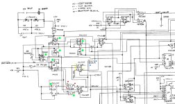
All the components marked green below test out good and I get the clocks expected on their respective pins.

C6 (marked in blue has a low on input-13 and thus a low on output-11. This effectively stopped me testing further down that path.

However, C6 (red) and C5 (yellow) seem highly suspect. See screenshots and text below.

2001-Clock - 01.jpg


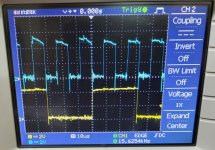
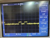
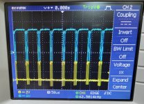
On C6 (red dots), I get the following signals on the two inputs. However, the output is high with the waveform in the second screenshot. This is clearly not right. Question is if C6 is faulty or if C5-pin-8 is pulling it high. The outputs of this C5 JK does give an output though. See second set of screenshots on the inputs of the second JK in C5 (yellow dots).

Inputs on Pins 4 and 5 of C6. Looks all good.
C6-4-5.jpg

Output on pin-6 of C6. It's high with the higher clock superimposed on top. This can't be right. Is this gate faulty or could it perhaps be C5 pulling it high? I do suspect C5 in any case. See below.
C6-6.jpg


C5 does give out signals on pins 5 and 6. Seems these are the Dis-On and Dis-Off signals. These go to the the inputs of the second C5 JK on pins 1 and 4. and looks as follows.
(CLK is a 125KHz signal from B5 and CLR is high.)

So, all the inputs have a signal and I expected an output on the outputs on pins 2 and 3. However, Q and /Q are sitting at 1 and 0.
But I'm not 100% sure if the Boolean logic dictate that the outputs should switch with these two inputs + plus the 125KHz clock.
Could it be that this, second JK is actually working correctly but is getting the wrong inputs from the first C5 JK due to pin-8 being permanently high?

Pin 1 and 4 of C5:
C5-1-4.jpg


It would thus seem that C6 and/or C5 is causing the symptoms?
I've got spare 7408, so can swap C6 but unfortunately don't have 74107s in the parts bin. Will have to go buy some.
 
C6 is a duffer I would wager.

Nice debugging...

I have lunch in a few minutes, but will give you a short explanation later if you need it.

The problem with C5 is the 'stuck' J input. Have a look at the datasheet for the 74LS107 JK flip flop and you should see why...

Dave
 
C6 is a duffer I would wager.

Nice debugging...

I have lunch in a few minutes, but will give you a short explanation later if you need it.

The problem with C5 is the 'stuck' J input. Have a look at the datasheet for the 74LS107 JK flip flop and you should see why...

Dave
Thanks Dave, also need to step out but will replace C6 a bit later today and revert.
 
Woot!!

Replaced C6 and now have V, H and Video on the Video connector! 🤩
.
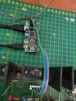
What I need to do next is to configure a HDMI adaptor so I can hook the 2001 board up on the telly on the bench.
.
When I first started working on the PETs, @Hugo Holden helped me design a proper composite video adaptor that conforms to the requirements for a video signal so it would properly display, especially on modern screens that suffered from tearing with the adaptors out there. This works very well, but I now have one of Hoglet's RGB2HDMI adaptors and this can work with any video setup, so no need to put a 16KHz EDIT ROM into the 80-column units. This makes it handy to work with both CRTC and non-CRTC boards. Here's a video by Chuck Hutchins on using this adaptor on various PETs.
 
Excellent. A nice, simple fix for once...

Dave
On getting video, for sure and thanks for all the help! But we're not out the woods yet. Suspect this is going to be a few seasons with a number of episodes per season effort! :biggrin:

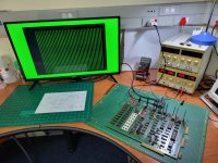
I've connected the HDMI converter up., using the profile Chuck created for the 9-inch boards.

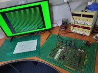
2001-Video-03.jpg

1st time I turned the system on, I go the following image, vertical bars
2001-Video-01.jpg

Subsequently, with numerous power cycles, I always get horizontal bars:

2001-Video-02.jpg

My understanding is that I should expect a screen filled with random characters, correct?

Would this point directly to faulty 2114s or could there be other logic issues? I did test the Char ROM in my reader and it verified, but - of course - it does not mean it's working in the board.
 
I thought is was too easy...

Well, you should get random characters until the CPU clears the screen.

I am happy with vertical lines (as per your first picture) but I am not sure what is happening with the horizontal ones...

Your vertical lines could be the parallel to serial shift register (B2) or the character generator ROM (A2). These would be my best guess.

If the character generator is in a socket, I would suggest removing it to see what we get.

All of the inputs to B2 should float high, and we should get a solid display screen.

Dave
 
Good idea Dave, to remove A2 and see what happens.

Jannie; in other computers I have seen vertical bars like that before when video RAM is defective and one of the output bits is stuck, though I have not seen this with the PET, but as you say the CHAR ROM might not be working in the board or its associated logic defective. It is odd though that it flipped over to horizontal bars after that, as the pattern, from the video signal point of view at least, is two very different frequencies. With your scoping skills and orderly approach to hardware debugging, I think you will get to the bottom of this in short order.

The topic has come up before about the video RAM in PETs, typically two 2114 IC's. It has turned out I think that in many PET repairs (including mine) that at least one of the 2114's has been defective. There is an argument, since there are only two of them, it might be reasonable, if video problems are happening, to socket them off the bat and fit known good IC's so as to eliminate them from the fault finding efforts. If already in sockets, that is moot.

On the other hand, with the main RAM, since there are so many IC's, and if soldered in, it is better to use diagnostic tests to narrow down the defective IC's.
 
Back
Top