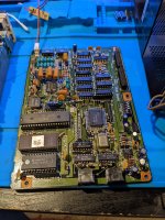
Based on the photo of the print, I think it should be doable. Most of the non-logic seems to be the TV-tuner and RS-232C level converter. Both the EF6803 and EF9545 are very informative. With schema's of other EF9545 applications, the video output can be found on other schema's of EF9545 applications. What is puzzling is the lack of any address decoder logic. So the address decoding is very rudimentary. The ROM is connected to the EF6803, the RAM to the EF9545. The EF6803 is probably used in mode 3, so it has only 128 bytes (internal) RAM, which is not much. A ROM disassembly should help.
What is not visible is the EF6803 crystal. Probably not a standard frequency, as it has to generate the Epson serial baud rate of 38400 Baud.
Attached is what I have so far.
Greetings,
Fred Jan
")