• Please review our updated Terms and Rules here

Honeywell 200 resurrection

RobS

Experienced Member
Joined
Sep 28, 2012
Messages
274
Location
Kent, England
I have been tracing the wiring from the external cable connectors to the light driver boards and from the boards to the lights, so now I know which input connections on the cable connectors operate which lights on the control panel. However, while doing this I had an unexpected result which actually solved another problem that I mentioned here not long ago.

During my tests the Central Clear button, later renamed System Clear, lit up but the Logic Training Manual, which describes the behaviour of the control panel, doesn't mention this button lighting up at all. One of my ex Honeywell field engineer friends explained this. After the control panels were first put into use on the basic H200 machines there was a field change made to include an illegal OpCode detection function. I mentioned here previously that I didn't know what happened when an illegal OpCode was encountered and in fact originally the result could be erratic depending on how closely the code resembled a valid one. Addition of the detection function resulted in the Central Clear button lighting up and the machine stopping, so presumably Central Clear then had to be pressed to clear the error condition. I did notice that the wiring for this lighting circuit had obviously been a later addition. I will of course include the illegal OpCode detection function in my machine now that I know about it.

By the way, when I wrote about the Central Clear / System Clear button before I confused it with the Initialise button. Central Clear did not clear peripheral operations but Initialise did, so this is why Central Clear was originally so named, because it only affected the CPU. Well, don't blame me as I was only a programmer and made a special point of not learning how to work the machine so that I was never asked to work shifts rather than nine to five.
 

RobS

Experienced Member
Joined
Sep 28, 2012
Messages
274
Location
Kent, England
By the way, regarding previous discussion of how SCRs might be used to control the lights in the control panel, now that I actually have the driver boards I removed one of the alleged SCRs from a board and tested it with my component analyser and it told me that it was a "low power thyristor", i.e. an SCR. I did this because one of my ex Honeywell field engineer friends insisted that the H200 power cabinets didn't provide any AC supplies apart from the mains, only DC and he even sent me the specifications of the power supplies for each machine configuration. Consequently I still don't know how the driver boards managed to operate the lights if the only power available to them was constant DC.

My friend and I debated the matter for some time before I did that test as the devices are marked 1595-4 and some standard devices with 1595 in their type numbers are evidently transistors but some are SCRs. These devices would have proprietary Honeywell component types anyway regardless of the actual manufacturer, of which there are several even across my four boards. Also these 3IDA0 boards evidently use SCRs but the later 5IDA0 boards, which were also Honeywell light drivers used in other equipment, used transistors. I know for sure because I have some.

So I have an AC /DC puzzle to resolve to get the panel working.
 

RobS

Experienced Member
Joined
Sep 28, 2012
Messages
274
Location
Kent, England
Is there a capacitor in the gate circuit at all?

If so, this can effect a switch off.

Dave
There is a capacitor so you're suggesting that the circuit may use reverse triggering. Whether that works depends on a number of factors but my component analyser did specifically describe the SCR as a low power thyristor, which may mean that it did try reverse triggering it during the analysis. Reverse triggering gets impractical in high power devices. The SCR drives two 14 volt 1 watt lights in parallel and the current is only about 160 mA, so if the SCR is designed for reverse triggering this is a possibility. I will bear it in mind when I fully trace the circuits as the biasing for the gates is complicated with several unknown inputs. Thanks for that suggestion.
 

daver2

10k Member
Joined
Jun 19, 2012
Messages
13,154
Location
UK - Worcester
It would be interesting to see the traced circuit though. That is the best way, rather than guessing of course.

A GTO thyristor is turned ON by a (positive) pulse and then OFF again by a negative pulse. The negative pulse can be generated via the capacitor.

Dave
 

RobS

Experienced Member
Joined
Sep 28, 2012
Messages
274
Location
Kent, England
Even when I have traced the circuit I may find several incoming power lines but not know the voltages that they originally provided, so a certain amount of guesswork may still be required. Once I have the full circuit I'll post it here for comment.

Anyway my wife and I always try to "keep Sunday special" and spend the time together instead of pursuing our individual activities, so I most likely won't be returning to the task until Monday. After over fifty years maintaining a vintage marriage deserves as much attention as maintaining vintage technology. It's just too easy to overlook that.
 

daver2

10k Member
Joined
Jun 19, 2012
Messages
13,154
Location
UK - Worcester
Is there just 1 (or 2) thyristors per lamp?

If 2, then the second thyristor could turn off the first if the capacitor was fitted between the two anodes. This would be designed to 'pull' the anode voltage of the thyristor negative wrt the cathode for a brief period of time, thus causing the thyristor to turn off.

Yes, it doesn't stop you thinking about the problem though :)...

Dave
 

1944GPW

Veteran Member
Joined
Apr 26, 2011
Messages
762
Location
Brisbane, Australia
Your project has taken on a whole new turn with the panel acquisition, awesome!
If you could post some high-res photos of both sides of the boards, the connectors and the general wiring loom on say Github and link it back here, you might be able to crowdsource some help or advice in figuring it out. At the least, I'm sure some constructive comments would ensue.
 

RobS

Experienced Member
Joined
Sep 28, 2012
Messages
274
Location
Kent, England
Dave, I should have mentioned that the only capacitor in the circuit is connected directly between the gate and cathode of the SCR, so that quite literally puts a damper on everything. That's hardly surprising given that Honeywell originally started their business making automatic dampers for stoves ...

Well. I did say that I go off topic and off the site on Sundays. Bye for now all.
 

RobS

Experienced Member
Joined
Sep 28, 2012
Messages
274
Location
Kent, England
Your project has taken on a whole new turn with the panel acquisition, awesome!
If you could post some high-res photos of both sides of the boards, the connectors and the general wiring loom on say Github and link it back here, you might be able to crowdsource some help or advice in figuring it out. At the least, I'm sure some constructive comments would ensue.
I've already roughed out a schematic of the boards so pictures wouldn't add anything and nothing can be determined from visual examination of the wiring loom given that all the wires are the same colour. The only way to trace the connections is through methodical electrical testing, which also verifies whether the switches and lights are still working.

I will be tracing the connections to the switches next because there are many of these and they are probably laid out in a logical manner, so that should be relatively easy, and once that is done I can focus on any connections still unidentified. I traced the light wiring first because it was easy to apply voltage to individual wires and watch which light if any lit up and hopefully the switch connections on the external connectors will follow a similar pattern to their corresponding light connections.

This is just the grunt work.
 

RobS

Experienced Member
Joined
Sep 28, 2012
Messages
274
Location
Kent, England
On the control panel I have now traced 79 of the 82 connections with the central processor and all 18 of the connections with the power cabinet but there remain nine connections on each of the light driver boards having wires that disappear into the wiring harness without any sign of where they emerge. Unfortunately these are all the ones associated with the gate inputs to the SCRs, so I am still no closer to discovering how the driver boards might work. I wondered whether these wires were cross-connections between the boards themselves but the directions in which they enter the harness do not support this idea. Given that apart from the boards the unit only contains lights, switches, one resistor and one capacitor the possibilities are distinctly limited.

Naturally I am not happy about any wires having only one end, so will persevere.

The power cabinet connector is a nineteen pin MIL-5015 type and I am in no hurry to fork out the money for a matching cable connector for it just now given that I don't have a power cabinet as such, only temporary bench power supplies, and the CPU and control panel can still work together without using most of these connections. No doubt if I ever get the machine to work then it would be appropriate to use the original connector for authenticity instead of bypassing it but for now I have already spent enough money just getting the control panel itself.
 

daver2

10k Member
Joined
Jun 19, 2012
Messages
13,154
Location
UK - Worcester
That's a tad annoying...

Can you post the power supply specification you were sent? I had a thought... It doesn't make sense using an AC supply for thyristors or SCR's. This means that a transformer with a full-wave bridge rectifier (but no smoothing capacitors) would be classed as a DC supply - but it still passes to zero, so would switch off the thyristor/SCR in the process...

Dave
 

RobS

Experienced Member
Joined
Sep 28, 2012
Messages
274
Location
Kent, England
Yes, that
That's a tad annoying...

Can you post the power supply specification you were sent? I had a thought... It doesn't make sense using an AC supply for thyristors or SCR's. This means that a transformer with a full-wave bridge rectifier (but no smoothing capacitors) would be classed as a DC supply - but it still passes to zero, so would switch off the thyristor/SCR in the process...

Dave

It won't help as just the voltages are given but no indication whether they were smoothed DC or not. However, I know for a fact that five of the supplies were smoothed as I use substitutes for those in my main memory unit. If I can't see any other solution then I will simply remove the smoothing capacitors from one of my original Honeywell PSUs, which didn't actually come from an H200 but are from the same era. I still need to find out what those complicated input circuits on the boards accomplish though. When I find the time I will draw up a decent schematic for the boards to illustrate my confusion.

I have had my share of puzzles with this unit. While tracing the connections from the circular 19 pin Mil-5015 connector I couldn't find anything connected to just one of the pins despite the thick power wires used on it being relatively easy to locate. Only when I was entirely mystified did I wedge the wires far enough apart actually to see the back of the mystery pin right in the middle of the connector and realise there wasn't a wire attached to it! What an idiot!

Having traced the lighting connections to all the illuminated buttons and error indicators I later realised that I had missed one but there wasn't an input line left to work it. What I had missed was the fact that the DC OFF / RESET button can glow white when it is acting as DC OFF and red when acting as RESET, so needs separate inputs to its white and red lights. At least this time I wasn't being such an idiot because I realised that the RESET button is only needed when there is a VOLTAGE error, so the red lights for the button were wired to the same input as the VOLTAGE error indicator. It hadn't occurred to me at first that two separate indicators on opposite sides of the panel would be wired directly together but it did make sense.
 

RobS

Experienced Member
Joined
Sep 28, 2012
Messages
274
Location
Kent, England
Last night in bed I think I worked out what all the circuits on the driver boards do but I will post the explanation later when I have traced the wiring to confirm my suspicions. In the meantime here is another detail.

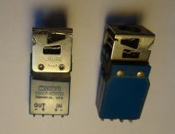
Several of the switch assemblies in the panel have small blue boxes attached directly to their standard three pin two way microswitches. These appear to be the ones that are described as one-shot switches in the parts manifest for the panel, so the boxes probably contain capacitors that supply the one shot pulses. Below is a picture of this type of switch. The contents of the box are encapsulated so it is difficult to tell exactly what components are present and how they are wired to the microswitch. The switch assembly is marked as MICRO microswitch type 2D644 but I can't find any information about this type. Can anyone else here?

No doubt eventually I will trace how the four connections on this type of switch are wired within the panel and be able to guess how it works but it would be nice to know the actual technical details if they are available.

One-shot microswitch.JPG
 

durgadas311

Veteran Member
Joined
Mar 13, 2011
Messages
1,700
Location
Minnesota
Interesting, those switch assemblies are very similar to ones I picked up at a surplus store in the late 70's. The button side was different than those used for Honeywell front panels, but otherwise they might have been interchangeable.

So are you thinking that this module provides a stable, short, pulse no matter how long the switch is depressed by the user? I'm guessing these modules have discreet components inside, rather than an IC like 74123 (or DTL equivalent). The other question is whether the output is "dry contacts" (like a reed switch) or whether it is a DTL/TTL (compatible) signal - or even some signal that is more crude. And whether earlier front panels did that "off switch" and these modules were only used once the technology became practical.
 

RobS

Experienced Member
Joined
Sep 28, 2012
Messages
274
Location
Kent, England
I tested the device with a component tester and only detected a capacitor. Then I dug out a hole in a spare one and only found one end of a capacitor. I think it's pretty primitive.

Anyway, now for the more interesting stuff.

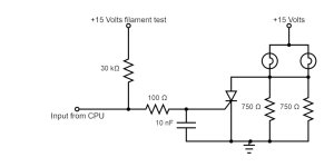
Having determined that many of the components on the driver boards are actually part of separate circuits, the SCR driver circuit is now ludicrously simple. See below. Clearly there are no gate turn off negative pulses involved, so the only way that the circuit can function is by being supplied with a fluctuating DC supply, e.g. raw unsmoothed rectified AC, to turn off the SCR. This would tend to synchronise the flashing of the lights with the mains supply but the actual patterns would be complex as a result of the filtered high frequency digital CPU input gating the SCR at varying points throughout consecutive half cycles. No doubt this interaction gave the control panel lights their distinctive appearance when the machine was running, something that people have mentioned in their recollections.

When the INITIALIZE button is pressed it feeds +15 Volts from the same light supply into all the filament test inputs with the result that all the lights (at least the ones that actually work) are forced on.

CPU light driver.jpg
 
Top