• Please review our updated Terms and Rules here

Honeywell 200 resurrection

Interesting, so the lights did not actually accurately reflect the work going on, but were modulating a half-wave or full-wave 50/60 Hz signal. Once a light turned on, it remained on the for rest of the wave. I guess that's not too different from what I had to do on my simulator, where I only snapshot the front panel lights every ~100mS (human perception of flashing).

Is that really 10 nano-farad cap on the gate? That would have been just filtering off high frequencies - but must not have significantly interfered with the activity signal from the CPU? Any idea what sorts of frequencies one would see on those CPU signals? Perhaps the computer was subject to a lot of RF interference (or glitches) and they needed that 10nF to avoid false triggering.
 
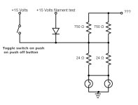
The circuits for the control and sense switch buttons differ from the buttons with lights driven by the CPU as the switches on the former are push-on-push-off latching ones that store their own state and are not affected by the CPU. Therefore they can directly control their lights without the need for SCR drivers. The circuits for their lights are shown below. On would expect the 750 ohm trickle current resistors to be connected to the 15 Volt supply but I haven't been able to determine where that connection goes yet as it doesn't do that apparently. As with the CPU light drivers the INITIALIZE button connects the 15 Volt supply to the filament test point to force the lights on.

Control panel light driver.jpg
The third type of light circuit is the one used by the power cabinet indicator lights in the AC and DC power buttons and the power error indicators CB (Contact Breaker), FAN and VOLTAGE. In this case the lights are also connected to ground on one side but are driven by connections directly from the power cabinet circuits on the other, so there are no electronic components needed in the control panel for them. Field engineers tell me that some of the lights in the control panel used 28 Volts instead of 14 Volts, so these may be those although I don't think the original parts manifest mentions two different type of lights, so maybe this was an afterthought possibly because relays in the power cabinet used 28 Volts.
 
Is that really 10 nano-farad cap on the gate? That would have been just filtering off high frequencies - but must not have significantly interfered with the activity signal from the CPU? Any idea what sorts of frequencies one would see on those CPU signals? Perhaps the computer was subject to a lot of RF interference (or glitches) and they needed that 10nF to avoid false triggering.

That's how the schematics software I used insisted on showing it although I entered 0.01mfd. The control panel directly displayed the main memory data and address registers when the machine was running and the main memory cycle time alone was two microseconds so the frequencies would have been around 500 kHz or more given that the control memory cycled four times faster to set up the values in the registers. Perhaps there was lower frequency filtering at the CPU end of the interface and that capacitor was just glitch-proofing as you say.
 
It seems that I have just received a clear warning that I have done enough work on the panel today.

I took all the buttons off the panel and washed them in biological detergent to remove the grime accumulated by fingers rubbing on them for decades. That also made it possible to clean the fascia with IPA to remove grime, fossilised labels and adhesive. Furthermore it made the light bulbs themselves visible so that I could check which ones were working.

I used my bench DC PSU to test the lights by connecting it to the main power block inside the case but only inserted two of the four light driver boards to avoid exceeding the PSU's maximum current. By this means I was able to identify and replace the faulty bulbs in half of the lights. In the process it also confirmed that the SCR circuits on those two boards were working correctly although, as anticipated, once triggered by the INITIALIZE button's filament test voltage the SCRs did not turn off again while fed with constant DC. This confirms that fluctuating DC is necessary to work the panel correctly. So far so good.

I then took out the first two boards and inserted the other two in their own sockets in order to test the rest of the lights. This time some lights came on as soon as the power was applied, which indicated that some SCR circuits on these boards were misbehaving. Raising the supply voltage gradually from a minimal level didn't stop this happening, so it didn't seem to be caused by spurious triggering when full power was applied immediately. To verify that the suspected SCRs were to blame I swapped over the two boards to see which lights then came on. In some cases the same SCRs were still misbehaving but other lights were also coming on prematurely. Now that I could accept and investigate but here comes the weird part.

On of the lights that came on was one from the previous test of the first two boards even though there was no driver board present to ground it through one of its SCRs. Also, despite my having already ensured that both bulbs in that light were working during the previous test, only one of the bulbs lit up! The two bulbs are wired in parallel at the holders with power permanently wired to one side and the other side wired to the socket for the driver board, which normally provides the path to ground to light the bulbs when it is in place. How then could a fault occur anywhere which resulted in only one bulb lighting up?

I took this event as a sign that it was time to call it a day and do something else entirely. I know when I'm beaten.
 
Last edited:
How many idiots does it take to change a light bulb? Just one in my case. I spent a good part of the day changing many dud bulbs in the panel and eventually almost all were working although a couple appeared to being having problems, possibly caused by the bulb-holders rather than the bulbs. However, then a calamity occurred as the panel shorted out entirely and was only saved by the current limiter in my bench PSU. Consequently I have spent much of the day splitting up the nice tidy cable harness and cutting the power bus wires at intervals to isolate the source of the short. I have now isolated the fault to four buttons on the bottom row of the panel and will investigate them another day. Ironically I suspect that the culprit is the STOP button and it certainly stopped me making any progress for a while.

Regarding my previous problem with a light coming on when it shouldn't have, This morning I suspected that one of the pair of bulbs had slipped out of its holder when I turned the panel upside down to change the driver boards and in the process it had shorted its case to ground, thus completing the circuit for the other bulb to light. Indeed, when I turned the panel on this morning I tried pushing the dead bulb firmly into its holder and it certainly did light up, so unfortunately I then had two bulbs alight that shouldn't have been. The short circuit across the entire panel has stopped me investigating this weird fault any further at present.

Over seventy years ago when I was about seven years old I started playing with light bulbs, switches, electromagnets, wires and batteries and that is how my interest in electronics started, so I find it amusing that all these years later my time should be so thoroughly occupied by little more than light bulbs and switches. Eventually I will get back to finding out how many dud SCRs I need to replace and then I may end up with a fully working control panel. At least the four sense switches now seem to be working correctly, so my progress to date hasn't been entirely senseless.
 
Last edited:
When I was in junior high school (7th grade - 1952) we had a shop class that dealt with almost everything. We were taught how to do Western Union wire spices, fix leaky faucets and replace the washers, and best of all, the wood lathe. The City of Detroit Department of Education would take donations of beat-up bowling pins and we would turn the tops into files handles and the large bottom portions became mallets. We also had a metal roller and soldering irons to make fancy cookie cutters. BTW, when school started right after Labor Day I didn't turn 12 until September 21st. For me, this was the period when I evolved from a little boy into a young man. The 8th grade brought on my favorite class - print shop. All this has nothing to do much with electricity or computers, but makes one wonder if hands-on in schools would not be a good thing. BTW turned 83 a week ago last Thursday. The Navy got me into computers back in 1974 and it's been a passion ever since.
 
All this has nothing to do much with electricity or computers, but makes one wonder if hands-on in schools would not be a good thing.
Yes! But all of that got binned as "vocational tech" in the 70's and not college-path education. Subsequently dropped from the curriculum, at least in my suburban area. I was fortunate to be able to take "shop" in 7th grade but after that it was slim pickings -- limited to auto mechanics in summer school. In 7th grade the mechanical engineering was rather limited, although at least we did drafting, printing, and real-darkroom photography.

On the down side, that was also the era of "home economics".

I don't recall Harper's, but I was definitely reading similar style/content books at the time. No local blacksmith, but I understood the concept just fine. We did have a local sawmill, rude and crude. Wonderful! By the 70's all of those books were getting culled from the school & public libraries :-<.
 
I am now down to the most defiant faults in the panel light circuits. For the time being I have set aside the fact that of the thirty-two driver SCR circuits eight appear to be faulty, but that is just a matter of checking over the PCBs whereas the wiring inside the case is far more challenging.

I have just taken a break for afternoon tea, being conventionally British, after discovering the nature of the fault that has been taxing me for some hours. It is the one previously mentioned where two bulbs light up all the time regardless of whether they should or not. I spent ages testing the circuits and wiring and could find no fault nor any short circuit that could cause the problem. Eventually I discovered that the fault only occurs when the back of the case is closed. Unfortunately I had only been testing the circuits with it open for access with the case face down, so I couldn't see the lights. As can be seen from earlier pictures the driver boards are mounted on the back cover, so all the wires to them rub against the edges of the case whenever the back is opened and closed. Evidently the insulation on a wire has rubbed through where the damage isn't visible and it is shorting to the case, which would be enough to light the bulbs. Some extra insulation between the wires and case should cure the fault. Just a small triumph in a long battle.
 
Oooo, pretty!

Dave

Yes, but until I fix the faulty SCRs and set up a fluctuating DC supply they don't go out, so at the moment they are only pretty. I took the photos quickly before any of them started failing. Many bulbs died in the making of this picture.
 
I have just found a video of an H200 running from 1964 on YouTube and spotted something different about the control panel. Can you see the difference? I have contacted my ex field engineer friends about it.

Also that is a lot of tape drives to be controlled by the machine in address mode two. I would have expected it to be using address mode three. Very peculiar.

 
Yours has an extra DISPLAY button of the far right section? We can't see the detail, so can't tell what those three buttons do in the video (e.g. whether there is no "DISPLAY -1" or perhaps no "DISPLAY" without change, or...)
 
Last edited:
I could imagine a fairly simple data processing program could involve 3/4 tape drives and fit in 4K. Although, it does look like A12 is also ON, so perhaps there is something more going on. But, you are able to compute Pi to 700 places using only 2K!
 
Interesting, I see a very early (Dec 1963 - April 1964) document on the H200 that seems to show three buttons there (two DISPLAY and one ENTER). http://www.bitsavers.org/pdf/honeywell/series200/model_200/H200Summary.pdf

A Jan 1965 document (http://www.bitsavers.org/pdf/honeyw...bs/DSI-391_Series_200_Summary_Description.pdf) shows four buttons (presumably three DISPLAY and one ENTER) in some photos while showing 3-button styles in others.

Sounds like maybe the first version(s) had the 3-button and it was quickly discovered that 4-buttons were needed to be practical. Unknown if that 3-button one might have been a prototype that was never shipped to customers (used for demo/photo-op only) or just an (one of many) early version that was held-back for display purposes.
 
A Jan 1965 document (http://www.bitsavers.org/pdf/honeyw...bs/DSI-391_Series_200_Summary_Description.pdf) shows four buttons (presumably three DISPLAY and one ENTER) in some photos while showing 3-button styles in others.
The DISPLAY-1 button was probably the afterthought. DISPLAY+1 would have been considered adequate for examining consecutive locations originally.

I noticed that one of the panels in that document had the full eighteen digits for the address, which indicates that it was designed for address mode four. However, I can only see what looks like two ADMODE buttons, at least one of which appears to be split in two, so apparently having three separate buttons there was also an afterthought.

On another subject, my concerns about SCRs not working was unfounded. Some lights were coming on as soon as power was applied because I had left the inputs from the CPU unconnected, so floating, and transient interference was evidently triggering some of the more sensitive SCRs. Grounding the inputs through a resistor cured the fault by suppressing the transients while still allowing the INITIALIZE button to fire the SCRs. Hence I can now deem all the light circuits for connection to the CPU to be fully working.

The next step will be to test all the button outputs to the CPU. The panel has inbuilt pull-up and pull-down circuits so that the outputs emulate standard digital signals to the extent that each button can support a fanout of ten standard input loads. The pull-down voltage is a little below ground potential and the circuits that provide this at a high enough current rating have been damaged by scorching on the PCBs, so I know that some repairs are necessary there. In contrast to the beefy pull-down, weak pull-up to all buttons is provided by just one small resistor and a capacitor mounted centrally on a small board easily visible in the picture of the interior shown earlier. Normally all buttons are providing pull-down but only those pressed at any time use pull-up, so this relatively feeble pull-up arrangement is adequate.
 
Back
Top