• Please review our updated Terms and Rules here

Honeywell 200 resurrection

BBtheEE ,

While testing the panel using a level DC PSU with all lights lit by INITIALIZE it did consume something over 6 Amps as you suspect. I can't directly measure the fluctuating PSU voltage that I am now using, so monitor it with my oscilloscope and the constant voltage transformer does appear to compensate for the large variation in current when the INITIALIZE button is pressed.

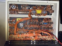
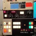
My H200 panel has two distinct types of lamps. Those connected to the CPU or directly controlled by the panel button themselves (the latter being the CONTROL and SENSE push-on-push-off buttons) are all type 382 operating from the nominal 15 Volt supply, components within the circuits dropping this to 14 Volts at the lamps. Those connected to the PSU, i.e. AC and DC ON and OFF plus the hidden error indicators FAN, VOLTAGE and CB (contact breaker), are type 387 powered from a separate 28 Volt supply. The 387 lamps use twice the voltage but half the current (40mA) of the 382 lamps (80mA), so both have the same wattage and light output. As the 387 lamps were directly driven by the interlock logic in the PSU cabinet the INITIALIZE button doesn't light them. I am told that sometimes engineers mistakenly replaced a 387 with a 382 but if they did it would have been blown by the higher voltage, so your mixture of 387 and 382 behind the same button looks like such a mistake and they should both be 387, I suspect.

The hidden indicators FAN, VOLTAGE, CB, PARITY and INTERRUPT are behind the fascia panel and only visible when lit. Of these INITIALIZE only lights PARITY and INTERRUPT. Replacing these lamps appears to involve removing the fascia, so I haven't bothered with them yet. Presumably they got far less use than any of the others, so lasted much longer.

The INITIALIZE button had no lamps because initialisation was virtually an instant operation while the button was pressed rather than a process that took a significant length of time. That is why some of the other buttons like INSTRUCT also didn't need lamps.

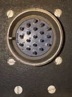
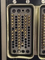
If any of the external signal connection data that I have traced is of any use to you then I will give it to you although I haven't actually typed it all up yet and it is just scribbled working notes until I do so. In particular the buttons with lamps running on the 28 Volt supply each have their own connection to the PSU logic on the circular power connector except that the red reset lamps in DC OFF that you mention are wired to the VOLTAGE error indicator lamps, so both always came on together.
 
Good to see that the CVT is alive and well! :)

Someone (probably me...I've been lugging this thing around for over 40 years) probably put the 382 lamps in the power switches. I found some 382 lamps on Amazon for a decent price, $75 for a box of 100 (individually they were something like $6.50 or something crazy like that). I don't want to have to have another power supply just for the AC/DC switches. Looks like I'll get to try my hand at pulling the red bulbs out after all as they are probably 387s.

It looks like Honeywell wired the canon (the circular power) connector the same for all machines (control panel or console), which makes sense since those circuits are probably the same for all models. Mine had a 19-pin canon wired to the AC/DC switches, FAN, CB and VOLTAGE lamps. I have an H2015 control panel in case I hadn't mentioned it before. It also had a pair of, if memory serves, 85-pin connectors; one for the basic portion of the control panel and another just for the diagnostic panel on top. All very modular and a good design, IMHO. The diagnostic panels varied somewhat from model to model. I recall the 2050A had a bunch more lights in it than the H2015. It actually had lights for the addresses in it but they were the tiny bulbs that weren't much bigger than a grain of rice (same as used in my H4200 panel and elsewhere like the M9 memory in Honeywell systems...if you search for H4200 you'll find my pics). I remember scanning and clearing main and control memory with the 2050A diagnostics panel and you could see the address lamps counting in binary, at least the higher order bits. It looks like you can do the same with the H2015 diagnostic panel but without the address lights. Also of note is that I'm fairly certain that the H2015 and H3200 control panels were identical (dad had an H3200 system...I wish I had saved that panel instead out of nostalgia).

I didn't realize until now that mine doesn't have the PARITY lamp like yours does. Instead, they opted to put a set of 3 lamps called CHECK FUNCTION that provided more detail. It has a lookup table in the lid for the type of error including odd parity, even parity, and strangely odd-even parity. There is also an over-sized ALARM lamp that you can see whether the diagnostic panel cover is open or closed. I believe the M9 memory drawers also had individual parity lights for each core stack.

The H2015 also has a SYSTEM ACTIVE hidden lamp although I don't know how it was used. I wonder if it was under hardware and/or software control. My guess is the former, but it seems like it would be redundant with the RUN light.

Thanks for the offer of the drawings (I did use a couple of your schematics) but I also reverse engineered the lamp circuits on the 31DA0 boards, of which I have 3. There is a fourth board, a 61DA6, that is for SENSE switches 5-8 and utilizes the same basic circuits as the 31DA0 boards which only support 2 SENSE switches. (The 1s might be a capital "I" and the 0s might be capital "O", it's hard to tell the difference, so I might have the board numbers wrong).

I reverse-engineered most of the PCB connector wiring and created a spreadsheet if you're interested though. I gave up trying to leave the panel intact since most of the switches went to one of the 85-pin connectors and the canon connector. I wasn't up for reverse engineering how they were wired so I didn't complete the documentation.
 
I agree about the crazy price for 382 lamps but maybe this is because they still crop up elsewhere such as in plane dashboards. When our company scrapped some Honeywell equipment I also raided the engineers' workroom and acquired boxes with 100 382 and 387 lamps in them, so hopefully they'll suffice for a good while.

The data connectors on your panel are evidently very different from those on mine, which has three 36 pin connectors. These are exactly the same as the 36 pin connectors used in the computer's backplanes to hold the logic boards, which is convenient as I have plenty of cable terminators that fit them, being similar at both the panel and CPU ends of the cables.

That 4200 panel looks daunting compared to the simple elegance of the H200 panel. The design philosophy of the two was clearly different. The H200 was designed to appeal to users unfamiliar with computers, so wasn't built like industrial equipment but more like something that wouldn't look out of place in a conventional office, hence the absence of tall cabinets. In fact the machine was apparently demonstrated in hotel rooms to show that it didn't even need air-conditioning although it's likely that they did check that the room at least had a Honeywell thermostat installed as it was sensitive to the ambient temperature. The H200 panel was reassuringly simple as opposed to confusingly complicated, so didn't score so highly in terms of blinkenlights as other machines. It's certainly complicated enough to be a challenge in my somewhat crazy project.
 
Ya, the connectors are definitely different. Below is a pic of what the H2015 control panel has (well, "had") on it.

I thought that most of the logic drawers used PCBs for the cable connectors, but it's been a long time. 😁 
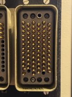
I definitely remember some that had multiple grey coax cables terminated that way, likely for sensitive analog signals. Although I would think that for things like disk and tape heads, they would get converted to digital inside the drives before sending them over such long distances.

That's very interesting about Honeywell's strategy with the physical design...I hadn't heard that before. I think it makes good sense. It certainly would open up a room with such short cabinetry (not counting tape drives). The countertops always had stuff piled on them, usually racks of manuals and stacks of punch cards (plus the occasional drink and ash tray!). I actually slept on one once back when I was probably 10...there's no way I could do that nowadays! 😅

The H4200 and H8200 were certainly different beasts from the rest of the series w/respect to the control panels and I think were the only two oddballs in the series. I'm pretty sure that my H2015 is identical in looks to the H3200 (they are very close at a minimum), but that was a big change going from the H3200 to the H4200. I never saw one in operation, unfortunately, but they looked very IBM-esq with all of the blinkenlights and switches. Those systems had two control panels and I think one of them was the same and is the one that I have. The other one was the same size but only had maybe a half-dozen pushbuttons...power and maybe a couple more (they looked nothing like the buttons on our panels, at least from the front). I only kept the one that looked interesting.

I wish I had kept a control panel from an H2050A instead. It also had the diagnostic panel similar to the H2015 but added a row of address lights like your H200 panel has but were the small ones like the H4200 uses.

IMG_2912.JPG
 
They look like regular Winchester MRAC75P connectors. The body parts and shells for MRACs are easy enough to find on eBay but it's the multitude of options for the pins and sockets (diameter, material, plating, tail type etc.) that are annoyingly complicated, and expensive.
They also require a special tool to fit and extract the pins (I tried making one once) but sometimes the connectors are listed as take-outs with wires chopped long enough to reattach your own extensions.
 
Last edited:
Ya, the connectors are definitely different. Below is a pic of what the H2015 control panel has (well, "had") on it.

But not any more? I always have to deliberate about which aspects of my home brew machine need to be similar enough to those on the original H200 to make it an equivalent. I have been obliged to take liberties with the internal logic as a consequence of the original components and schematics being unavailable but I will try to make all external aspects, e.g. the timings and behaviour of instructions and the interfaces with peripherals, when I eventually get around to providing any of these, replicas of the originals. Whether the control panel is peripheral to the CPU or an integral component is debatable and certainly when I discovered how expensive (in terms of my project budget) the correct MIL-DTL-5015 power connector for my panel would be I did consider replacing that existing circular connector with something cheaper.

My power supply unit will be nothing like the original although I will try to stick to Honeywell 1960s style technology and ditch the switch mode PSUs that I am currently using as temporary bench supplies. Nevertheless I have bought the matching 19 pin MIL-DTL-5015 connector for my panel now, although currently it only has two wires attached to it, but at least I can now use the panel exactly as it was supplied to me without any modifications at all being necessary. It is fortunate that the external logic connectors are simply H200 standard PCB sockets although the PCBs inside the panel actually have different sockets and pin spacings even though they have almost the same number of pins, which is a nuisance when it comes to bench testing them outside of the unit. Having remarked about the consistency of the components used in the H200 I find this detail perplexing but the iconic control panel may indeed have been developed separately as a peripheral component, its appearance, layout and functionality clearly having been a separate design exercise with even its shape and size being relatively independent of the layout of the power cabinet on which it was mounted. It makes one wonder how many compatible plug in design prototypes were tried out before the final design was adopted, the impact of the computer's overall design having been a key aspect of the original 1960s marketing strategy. This was made evident by Honeywell employing an artistic design expert on all aspects of the development aside from any more technical design work.
 
They look like regular Winchester MRAC75P connectors. The body parts and shells for MRACs are easy enough to find on eBay but it's the multitude of options for the pins and sockets (diameter, material, plating, tail type etc.) that are annoyingly complicated, and expensive.
They also require a special tool to fit and extract the pins (I tried making one once) but sometimes the connectors are listed as take-outs with wires chopped long enough to reattach your own extensions.
I was able to find some info on them and from what I saw, you're right...they look pricey and I didn't want (or need) to mess with the bulkiness and cost.
 
But not any more?
Ya, I removed them along with a bunch of the wiring. At first I was going to try to keep it intact, but the more I looked at it, it was going to be more of a project than I wanted to attempt. If all of the switches and wires had gone to the 4 PCBs inside, I would have done that, but such was not the case. I ended up gutting a good chunk of the wiring but used the existing wires where possible and rewired the rest with leftovers from the gutting. I doubt anyone was going to attempt to rebuild an H2015, but then again, I didn't think anyone would try to rebuild an H200 either! ;)

Here are a couple pics of the before and after. The green board is my design with an Arduino on it. The other 3 boards are Honeywell but don't do anything other than look pretty. 😁

I still have some work to do, mainly for the switches, but I do have the lamp drivers working. I can post more pics if you're interested
 

Attachments

  • IMG_2898.JPG
    IMG_2898.JPG
    3.8 MB · Views: 15
  • H2015.jpg
    H2015.jpg
    1,021 KB · Views: 15
  • H2015 lamp test.jpg
    H2015 lamp test.jpg
    2 MB · Views: 15
They look like regular Winchester MRAC75P connectors
I found some pics that I took of the connectors. I kept everything, including leftover wires, just in case I ever pull a Rob and try to assemble an H2015! ;) 😁
 

Attachments

  • IMG_2915.JPG
    IMG_2915.JPG
    1.6 MB · Views: 2
  • IMG_2914.JPG
    IMG_2914.JPG
    1.5 MB · Views: 2
  • IMG_2913.JPG
    IMG_2913.JPG
    1.5 MB · Views: 2
Can that be because the unit was reworked? I recall using real T&B ty-raps in the 1960s, but that was mostly for on-site field servicing. Cable lacing, particularly for telecom and mil-spec was very much the rule for manufacturers. Curious thing is that the nylon cable tie was invented for the aircraft assembly workers; traditional cable lacing was hard on the hands.
 
It's possible, but unlikely IMHO. Certainly not in the field since there was no trace of any lacing (see the first photo), even in the hard to get to areas of the diagnostic panel. I took everything apart and gave it a good cleaning. Honeywell ty-wrapped this thing like crazy, even if only a pair of wires.

Maybe it was reworked at the factory from some other model into an H2015? If that were the case, I would think they would have just laced it. The diagnostic panel was pretty much wired independent of the main panel (the lower section which was common to all models) except for some of the lights were driven by one of the four PCBs inside.
 
The 1960s were a transitional period, so it's quite possible that Honeywell saw fit to move to the newer technology. As speed-of-light issues became more of a problem, neat cable lacing went out the window.
Computer_CDC2.jpg
 
It is fortunate that the external logic connectors are simply H200 standard PCB sockets although the PCBs inside the panel actually have different sockets and pin spacings even though they have almost the same number of pins, which is a nuisance when it comes to bench testing them outside of the unit.
I noticed that too about the pin spacing being different...I never knew why they did that. The only thing I can think of is that the backplanes for the logic drawers were probably custom and made up of multiple large blocks that held several boards (I don't remember how many boards plugged into a block, maybe 8?) that couldn't be used in the control panels, so they used off the shelf connectors for those boards. Those blocks were wire-wrapped too, so probably not convenient for a control panel anyway.

I recreated the pin spacing and board outline for the control panel PCBs, they match rather well. The board was originally going to replace the four that were in there until I decided to go this route instead and use dual-row headers for the wiring. I had already done the work so I left the edge connectors in the design but not connected to anything to see if I got it right. This was my first PCB with an edge connector and a specific outline so it worked well as a trial run for future projects.
 

Attachments

  • H2015 PCB - bare (top).jpg
    H2015 PCB - bare (top).jpg
    817.1 KB · Views: 4
  • H2015 PCB - bare (bottom).jpg
    H2015 PCB - bare (bottom).jpg
    731.8 KB · Views: 4
Last edited:
The 1960s were a transitional period, so it's quite possible that Honeywell saw fit to move to the newer technology. As speed-of-light issues became more of a problem, neat cable lacing went out the window.
Nice pic! Imagine making ECO changes to that! 😅

I don't recognize the machine. CDC?

Cray took that to an extreme and got great results. I read where they were a real pain to wire at the factory as well as rewire in the field.
 
Nice job, but if you're going for the authentic, shouldn't you be using linen cable lacing (https://en.wikipedia.org/wiki/Cable_lacing) rather than Ty-wraps? The linen stuff is still being sold.. Nylon cable ties look so klunky...

My H200 panel pictured previously HERE also has nylon cable ties which are possibly the originals although there is also some lacing. The H200 cable harnesses also from the early 1970s that I acquired had waxed lacing as you say. I was surprised about those nylon ties but that supports my previous remark that the control panels may have been built by a separate team from those working on the rest of the machine. I have bought some waxed nylon lacing cord so that I can reproduce both techniques in the appropriate contexts.

One possible explanation for the different styles is that the cabling within the control panels may have been built up in place rather than as a separate harness. I am aware that some labour-intensive work such as manually wiring the magnetic cores in core memories and assembling cable harnesses was not done in the USA but by an offshore company in Barbados where rates of pay were no doubt much lower. At the end of the 1960s this company was bought from its American shareholders by a British company, Plessey I think, and they invested in updating its production methods. I have examples of magnetic core planes made both before and after the change of ownership and those before were clearly hand made while those after appear to have been machine wired. For Honeywell the task of producing a computer that could compete with the IBM 1401 on both performance and cost was quite a balancing act, which is why all the details of its design and marketing fascinate me.

By the way, I have been invited to join a Makerspace group locally and hope to get to their next meeting later this month but most of my project work is just too bulky to move around. I may be able to share some ideas though and the H200 PCBs are all very small, so I can certainly take examples of that side of the work. Even the core memory modules are highly portable although the seventy or so support PCBs needed to run them along with their backplane aren't and the five PSUs needed as well are definitely staying at home. Perhaps what I too need is an "offshore" group to do some of my labour-intensive work for me ... hmmm

I didn't think anyone would try to rebuild an H200 either! ;)

Here are a couple pics of the before and after. The green board is my design with an Arduino on it. The other 3 boards are Honeywell but don't do anything other than look pretty. 😁

With the emphasis on the word "try" I suggest.

I have an Arduino mounted on a standard H200 PCB that I use as a USB interface between my H200 backplane and my laptop solely to run tests. This has enabled me to run test scans across the whole 8K main memory with the results listed on my laptop but I will not be including the Arduino board in the final machine, only for tests during development.

I see that your panel used the same 3IDA0 boards as mine, but apparently no longer. I'll know where to come for spare parts for mine then. I also see that those boards have the same burn marks as mine around the pair of high wattage resistors. On one of my boards this burning had actually broken the tracks on the reverse of the board and I had to repair them. I have determined that the purpose of those resistors was, in conjunction with forward conducting diodes, to drop a standard -15V supply from the CPU down to around -1.5V for use as the pull-down source for all the switches on the panel, each 3IDA0 board serving a group of switches. As all the switches were normally in the pull-down state that meant that those resistors were taking the full current including the current through the clamping diodes all the time. That current was set by the choice of resistor values used to enable each switch to have a ten way fan-out regardless of the actual load on it, around 14mA per switch. I am not convinced that the ten way fan-out was necessary as the interface for the panel on the CPU backplane probably only used single gates to receive the signals, but it was evidently just provided as a standard. This also supports my view that the design work on the control panels wasn't customised to relate to the design work on the CPUs and the 3IDA0 boards were just put in as standard modules.

I may reduce the voltage supplied to these resistors at the external interface of my panel, which will reduce the heat damage to the PCBs while not changing the pull-down voltage clamped by the diodes, only the average available fan-out of each switch. While attempting to preserve the essence of the original machine I am not averse to eliminating some of its deficiencies provided that I do not introduce evident anachronisms like microprocessors, tempting though it may be. Whether I am a perfectionist, idealist, realist or masochist remains to be seen.
 
Back
Top