• Please review our updated Terms and Rules here

KIM-1 Repairs continue

That's a weird one, alright. Cute, but weird. My question would be why on earth anyone would do it that way.

There's never been a time in recorded history (and I checked all of it) when jellybean HCT has been on allocation,
so as clever a little trick as it was, I don't get why someone would do it because they could then put either chip
down in that location. If it were me laying it out, I'd use the 08 and keep a couple of spare gates available.
I have never looked up supply issues in the past on 'HCT SOIC chips.

But there is a very interesting one, that is well documented and even in the manuals of some vintage computer boards from the late '70's, including the Matrox ALT-256 and ALT512 S-100 video cards.

Apparently, back in the late 1970's, due to the "explosion" of many manufacturers using 74LS IC's , many went out of stock a "shortage", at least in North America.

So they advised in the manuals, to fit plain 74 IC's in their place if the LS were not available (but the didn't say put up with the higher current consumption).

But here is the interesting thing in my view and it applies today:

When some very popular technology is surpassed, like LS74 replacing plain 74, it leaves behind many hundreds of thousands or millions of parts, like the plain 74 series TTL's. No "new" designer wants them, they are power hungry and "old hat". But oddly a wonderful silver lining.

The advantage is you can still get them.

A lot of modern IC's become obsolete at the drop of a hat. By the time you get something to the market, the part you used is now unobtainium.

So, I learned the "trick of using obsolete parts" where there is plenty of World stock. Say if it was 1985 I'd use the plain 74 chips not LS, but now I'd use DIL package HCT, because nobody else is using them.

You'd never guess what, a while back I made a project for a competition, where the prize money was funded by Australia's Dick Smith. My entry won the prize. It was to create an unbeatable Tic Tac Toe computer. Dick smith had made one back in the late 1950's using spare parts from a Telephone exchange.

I did it with now vintage DIL package 74HCT chips, for low power consumption and battery operation, also no CPU or clock, because cmos using static conditions has extremely low power, it was a "Static Computer".

The only "modern part" used in the design was a Hall Effect device, and before the article was published in Silicon Chip magazine, this new Hall device had become "obsolete" and a substitute had to be found (how ironic). All of the other "vintage devices" were still readily available in the many thousands:

www.worldphaco.com/uploads/THE%20STATIC%20TIC%20TAC%20TOE%20COMPUTER.pdf
 
Last edited:
I have never looked up supply issues in the past on 'HCT SOIC chips.

But there is a very interesting one, that is well documented and even in the manuals of some vintage computer boards from the late '70's, including the Matrox ALT-256 and ALT512 S-100 video cards.

Apparently, back in the late 1970's, due to the "explosion" of many manufacturers using 74LS IC's , many went out of stock a "shortage", at least in North America.

So they advised in the manuals, to fit plain 74 IC's in their place if the LS were not available (but the didn't say put up with the higher current consumption).

But here is the interesting thing in my view and it applies today:

When some very popular technology is surpassed, like LS74 replacing plain 74, it leaves behind many hundreds of thousands or millions of parts, like the plain 74 series TTL's. No "new" designer wants them, they are power hungry and "old hat". But oddly a wonderful silver lining.

The advantage is you can still get them.

A lot of modern IC's become obsolete at the drop of a hat. By the time you get something to the market, the part you used is now unobtainium.

So, I learned the "trick of using obsolete parts" where there is plenty of World stock. Say if it was 1985 I'd use the plain 74 chips not LS, but now I'd use DIL package HCT, because nobody else is using them.

You'd never guess what, a while back I made a project for a competition, where the prize money was funded by Australia's Dick Smith. My entry won the prize. It was to create an unbeatable Tic Tac Toe computer. Dick smith had made one back in the late 1950's using spare parts from a Telephone exchange.

I did it with now vintage DIL package 74HCT chips, for low power consumption and battery operation, also no CPU or clock, because cmos using static conditions has extremely low power, it was a "Static Computer".

The only "modern part" used in the design was a Hall Effect device, and before the article was published in Silicon Chip magazine, this new Hall device had become "obsolete" and a substitute had to be found (how ironic). All of the other "vintage devices" were still readily available in the many thousands:

www.worldphaco.com/uploads/THE%20STATIC%20TIC%20TAC%20TOE%20COMPUTER.pdf
It is also possible that the chip was put in there by mistake. Since, it didn't cause a failure no one noticed it was the wrong part. When I worked at Intel ( no worse of better than any place else ) I came across several times when the wrong part was installed. Some I could excuse like putting a glass zener diode in place of a glass signal diode. It wouldn't have been an issue but the zener voltage was less the the signal it was supposed to block. I was used in a balanced mixer for a phase detector in a PLL of a disk drive controller.
Getting a different part put in that wasn't on the original parts list was not something that didn't almost take a written approval all the way up to the CEO. I have a story related to that I could tell you some time.
Dwight
I guess that is possible, but it is the only case I have every seen where the way the chip was wired allowed another chip type to work. Generally in logic IC packages the gates are used for different applications here and there in the circuit. In the original case I think that they had 74HCT00's and needed two AND gates not NAND hence the use of two of the gates used as inverters, then freakishly making that pin-pin compatible with the 74HCT08.
 
I guess that is possible, but it is the only case I have every seen where the way the chip was wired allowed another chip type to work. Generally in logic IC packages the gates are used for different applications here and there in the circuit. In the original case I think that they had 74HCT00's and needed two AND gates not NAND hence the use of two of the gates used as inverters, then freakishly making that pin-pin compatible with the 74HCT08.
If done intentionally, it should be noted that a AND gate has slightly more delay than a NAND gate. In most cased, there is no effect but one never knows if anyone looked at this other than the engineer that designed the circuit. I can believe that it might have been done intentionally but knowing the number of times I've seen wrong parts, I'm giving it a 50/50 chance it was just the wrong part.
Dwight
One classic example has to be the right part & fitted the wrong way. One of my Philips radio frequency generators had a power supply electrolytic installed backwards at the factory.

Many years ago I repaired a VCR , it had a CPU operated system control and an array of diodes on the push button control panel. Every now and again, some combination of switch operations would cause it to go into alarm mode, and the CPU strobed all of the LED's on the panel like the car on Knight Rider. It turned out that one of the signal diodes was installed backwards at the factory.

Another factory I worked in, back in the 70's making car radios, one came off the production line with terrible audio cross over distortion, the reason is that one of the bias resistors in the output stage was a 56k when it should have been a 5.6k, somebody mistook an orange for a red.

A 1948 vintage shortwave tube radio I have ; I went to perform an alignment on it, and noticed that one RF transformer wouldn't peak on one band, because a wire link connecting it to the rotary switch was left out at the factory. Yet it passed and escaped the factory doors and the problem wasn't picked up for 30 years.

In my SOL-20, somebody crimped the spade terminals that plugged onto the the bridge rectifier, around the plastic insulation of the wires and the connections were only just touching. And that was hiding under the insulating sleeves. It caused the power to randomly and transiently drop out and it corrupted some disks I had made with the N* controller board. I would not have found that easily, but I had installed a digital meter module on the 8V rail and saw it transiently blink off, when the disk corruption fault occurred.

As I writing this I'm remembering more and more examples.

It seems that there is no end of silly mistakes that can be made at the factory.
 
I just saw these came up on ebay.. so I grabbed a couple.

Hopefully one day someone will figure out how to cram the replacement into the shell of a 6530 for appearance purposes.
Yes I agree with that remark, somehow, as it is, it doesn't look period correct for a KIM-1.

Part of of the art of repairing vintage computers I think, is to try to find a way to do it with parts that existed at the time the computer was made.

I prefer that, even if it has a Frankensteinian quality to it, rather than solutions that look like somebody solved the problem with a modern uP or some super compact device that didn't exist when the vintage machine was made, like the anachronistic notion of putting a Datsun Bluebird motor into a model T Ford, or a PWM controlled electric motor into a 1970's Datsun, or perhaps a yet not invented anti-graviton propulsion system into a Tesla.
 
Still, the peripherals will be important. I did get some of Bob's last stock of KIM I/O board PCBs before he passed away. Unless someone is making these again, I suppose I should sit down and try to put one or two together.
 
Yes I agree with that remark, somehow, as it is, it doesn't look period correct for a KIM-1.

Part of of the art of repairing vintage computers I think, is to try to find a way to do it with parts that existed at the time the computer was made.

I prefer that, even if it has a Frankensteinian quality to it, rather than solutions that look like somebody solved the problem with a modern uP or some super compact device that didn't exist when the vintage machine was made, like the anachronistic notion of putting a Datsun Bluebird motor into a model T Ford, or a PWM controlled electric motor into a 1970's Datsun, or perhaps a yet not invented anti-graviton propulsion system into a Tesla.
Not to criticize the creator as I'm grateful he did anything at all, but if it were me I'd leave off the soldermask - especially modern colors like that dark blue. Not that these would ever look natural but the KIM doesn't have a soldermask so having these big blue things protruding doesn't really sell it.

All the same, grateful I can finally find out if the ROMs are a problem or not.
Yes, that is a very good point, if the part is for "diagnostic purposes" rather than restoration, may as well have the most modern parts possible and what works,works, because the issue of period correct parts doesn't matter at all.
 
Part of of the art of repairing vintage computers I think, is to try to find a way to do it with parts that existed at the time the computer was made.

I'll see your "period appropriate components" argument, and raise you a "period appropriate techniques" wrt reproductions.

As I've indicated previously, a reproduction should not be considered true unless it was done using the techniques used for
the creation of the original. So if you're laying out a PCB, EDA is not on the menu for boards done (roughly speaking) prior
to the mid-80s. Turn on that light table and tape it like a man.
 
Oh - back to the actual subject at hand, though: Dwight sent me his 6530/32 boards and I've recreated the schematic.
It took some back-and-forth with him to get a bunch of details right, particularly in getting the pins and functions aligned
with his PAL. I'll be posting the schematic (I added it to my drawing of his diagnostic board) and the PAL details soon.
 
The post:
on post 38, you can see the rats nest of my first try at the 6530 to 6532. You also see the small boards I made to go under the 6532.
On the next page you can see the complete working KIM-1 with the 6532 stacked in top of the two boards and two sockets.
I regret to say that I lost the design work while trying to save the design. I've sent two of the spare boards to another member and he has recreated a schematic for the adapter. I'm not sure of his intent but it may be to recreate more boards, with some suggested changes to simplify them. They are really tricky to assemble because of the requirements I had to fit under the 6532.
It took 2 boards as one board was used for the scrambling of the pins 6530 to 6532. The other board had the two active parts needed, A PAL and the small EEPROM.
It would be technically possible to reduce the height if one removed the socket and soldered it all to the KIM. Since it all hides under the 6532, it looks a lot better than the larger FR4 boards used by others.
Of course, using the EEPROM, you'd need to have the debug board as well to know that you were replacing, what was broken, as well as programming the EEPROM.
Dwight
I should note that Circa77 also made a regular .PLD file for the PAL. I just used the data sheet and created the file by hand. I should note that the picture on 39 had an extra wire coming off it. That was because the original PAL code had the Phase 2 clock inverted.
Dwight
 
I just saw these came up on ebay.. so I grabbed a couple.

Hopefully one day someone will figure out how to cram the replacement into the shell of a 6530 for appearance purposes.
I wonder if he pre-programmed the EEROM. For my board, there were a number of address pin swaps in order to program it from the KIM-1 as well as routing issues.
( in other words, the addresses are not 1:1 and nether are the data lines ). This would make pre-programming a little difficult as the data file would need to be scrambled. I didn't need to do that on mine since it was programmed on the KIM and it just had to match the same wires for programming as used for the functional KIM.
Dwight
 
To clarify: I have no present intent beyond regenerating the documentation - I just wanted to do it for fun. Yeah, we can have some weird ideas about where to find "fun".

Dwight sent me a pair of bare boards as well as a completed assembly that had been somewhat hacked apart, but was still useful in doing the schematic.

Assuming my KIMs have good 6530s, I don't expect to do a layout (of course, if any are bad, that can change). I've only tossed out some vague suggestions to Dwight about the layout; if it were me, I'd opt for the smallest-footprint PLD and E^2 possible and try to stack the boards together with headers, perhaps 2mm, because it's not within my design philosophy to make unserviceable modules - much better to devise a stack that can be unstacked. But that's just idle speculation at the moment.

As for the PAL, he also proviced his artisanally-crafted JEDEC file, which I ran through a disassembler that came with an old set of DOS tools from National to get the equations. When I get a few minutes I'll push it through CUPL to complete the documentation, then post the lot here.
 
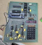
I got and installed the 'Retrospy' 6530 replacement boards. I replaced U2 first.. no dice. Then I replaced U3. No dice. This board just does not want to work.

There are only 4 chips in the tape i/o area that haven't been replaced. Everything else has been swapped/tested.

Perhaps one of the retrospy adapters are not working, but I doubt it. I guess next step is what I tried to do with the MMD board - go pin by pin against the schematic and verify all are good. This must be a problem with the board itself.
 

Attachments

  • 20240414_143656.jpg
    20240414_143656.jpg
    2.3 MB · Views: 3
Ah! I might be closer than I thought. I gently flexed the board while pressing reset and several times got parts of a display, which is more than this thing has done.. ever. In testing I seem to have found at least one short between RAM address lines.. so I'll spend a bit more time tonight carefully checking and removing any others I find.
 
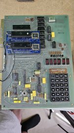
She works!

So it appears it had a couple of issues going on. The 6530-002 is definitely dead. Once I got it working I swapped back and forth a few times between the Retrospy adapter and the ROM and it's clearly not working.

Compounding the issue was my horrendously bad socketing job for the RAM. I cleared a dead short there and then also discovered the socket for U9 is a bit wonky. Pressing hard on U9 allowed the computer to function. I did some more checking to make sure the formerly shorted address lines weren't shorted or changing status as I pressed.. they weren't. Checked continuity from top of RAM leg to pad on the other side. Looked good. Couldn't figure it out. Tried swapping U8 and U9 RAMs.. the KIM wouldn't start up correctly no matter how much force was applied. I swapped back.. now it works with no assistance from me.

I'll have to mess around a bit more to be sure I've fixed it.. but wow. This is the first time this board has worked since I got it over a decade ago! It's too bad the U2 ROM is dead but at least the retrospy replacement isn't too large. Now time to try some programming!

Thank you to everyone who helped out with this, especially daver2 and Dwight! This gives me hope I can still figure out that blasted MMD-1!
 

Attachments

  • 20240414_194641.jpg
    20240414_194641.jpg
    2 MB · Views: 7
Back
Top