• Please review our updated Terms and Rules here

Neglected PET needing some love

Given that the garbage pixels resolved themselves as the computer ran longer and now no longer seems to do that makes me wonder if one or more of these electrolytic caps are dried up. also I'd like to find the correct rom images so I can compare CRCs.
 
There is a large collection of PET firmware files on zimmers.net. Not knowing what your machine has in it, I can't point you to the specific ones you want.


Unfortunately the files do not come with checksums or CRC values attached, so the way to do this is to load the relevant .bin file into your EPROM programmer's hex buffer, then put the matching ROM from your machine into the programmer's socket and then do a VERIFY. If the content of the ROM matches the file image of it held on zimmers.net then it will pass the VERIFY test.

When reading the ROMs you will need to select an equivalent EPROM as the device type, so for the 4K types you would read them as a Hitachi or Texas 2532. (Not 2732, as the pinout is different).

When reading ROMs in an EPROM programmer be very careful not to accidentally select the PROGRAM or AUTO operation, either action will apply a high programming voltage to the ROM and kill it instantly.
 
Let's go through a few basics before this thread goes awry...

Is the screen synchronised on your display screen? if it is, the video system is largely working. if it isn't, you need to identify whether the problem is in the PET or the display/adapter. In this case (with your oscilloscope) you have demonstrated that the H and V signals are correct. So, if the video signal is NOT synchronised on the display, the problem must be outside of the PET.

There are two potential issue now with the individual graphic 'cells' on the display. If they look like the Roman or Klingon language then the problem is usually down to the PET's character generator or parallel to shift register. If this 'fixes' itself, it is either a socket issue (if the character generator is socketed) or could indicate a temperature or age related issue. Keep an eye on this during your testing. If it does it again, take a quick photograph of it and post it for us.

if you have 'valid' characters randomly displayed on the screen, this is usually due to the PETs 6502 CPU not initialising the screen characters. This may be due to faulty RAM, faulty ROM or the inability of the CPU to actually write to the video RAM. There are too many unknowns to make any determination of the reason fro this at the moment.

By looking at the Commodore part number on the ROM, you can download the binary image for it from the Zimmers website. From this, you can confirm whether the ROM is potentially good or bad. I also present the 16-bit checksum in my PETTESTER documentation.

If the ROMs are socketed, all well and good. if not, I would avoid desoldering them just to identify if they are good or bad. Wait for my PETTESTER and this will identify this.

Dave
Yeah the screen is synchronized as far as I can tell. One behavior the RGB2HDMI has is if the sync is wrong then the screen flashes off and on unless you bring up the on-screen menu. This is what was happening before I dialed in the settings and I can make it happen by switching to a mismatched profile (like the c128) but with the profile as it sits now there's no flashing and it seems to be a valid sync.

Three of the roms are socketted and three aren't. I have some 2716 eproms on order so I'll wait until that arrives and write the pettester to it and run that before I try anything else. Although I guess I can take a look at each of the socketted chips and make sure both the pins on the chips and the sockets themselves are making good contact. I've already pulled those chips out, sprayed some deoxit in there, and replaced them but doesn't hurt to try again.
 
Last edited:
It's been a while since I've posted a video showing what the PET is doing now so here goes.

First boot up is cold, after a little over a minute the characters resolve themselves and become stable. After subsequent reboots I see "ready.reready.reready..."

I tried hooking up a keyboard and trying to clear the screen with multiple "returns" and even type in a simple program to print X's repeatedly to see if I can get anything to change but no change is noticed so I'm assuming it's not initializing to the point where it'll accept/respond to keyboard input.


I also tried some simple probing around with one of those laser thermometers and found some things that seem interesting to me but maybe is expected I'm not sure:
  • The small 7605 voltage regulator never gets warm
  • One of the two large voltage regulators never gets warm
  • One rom chip in particular gets very warm (about 40 deg c) this is UD8
But this could just be normal or at least normal given whatever the computer is doing right now.
 
Last edited:
That video is very telling...

Note that (horizontally and vertically) the sequence of characters repeat after every 8. The "Ready." is not being printed multiple times - it is just that the same set of 8 characters are being repeatedly displayed. That is my assessment at any rate based upon the information I have presently.

This indicates (to me) a problem with either the display multiplexers (UC8, UC9 or UC10) or the CRTC. Less likely the CRTC than the display address multiplexers.

All of the initial 'snow' indicates to me that this starts out as an intermittent fault - with the address line(s) sometimes working and sometimes not - giving the impression of the strange character behaviour. I suspect the behaviour changes once the device(s) warm up - hence a hair dryer and some targeted freezer spray could be used to find the faulty device(s).

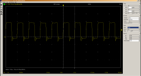
I would scope the TAn outputs from the CRTC to the display address multiplexers (to ensure they are nice stable square waves) and then scope the SAn signals from the display address multiplexers (once the devices have warmed up and the problem 'goes away') to see if any of these signals are 'stuck' high or low.


I would, therefore, stop worrying about your HDMI box of tricks!

The 7905 (not 7605) is the -5V regulator and only provides voltage for the DRAMs. This usually doesn't get warm at all. 78xx = positive regulator, 79xx = negative voltage regulator, XX = the voltage it regulates to.

UD8 (address $Dxxx) being hotter than the rest could indicate an issue with it - but 40 deg C is not (actually) that hot. It could just mean that that is where the CPU is executing instructions whilst waiting for you to type something! This ROM would then be accessed - with the others not - making it warmer. So, I think, normal for what the computer is doing right now is on the money.

Dave
Thanks! I'll scope that out. I did notice if I just let the computer sit for a good long while (like 20+ minutes) and power-cycle that the garbage characters return but I still feel there's a temperature component.
 
Okay below this is the first line (TA0). The other lines looked very similar with the unstable voltage in the low states but after letting the machine warm up they got more square (see video)
1665406351075.png


Before probing I also did a simple continuity test for each of these lines between the CRTC and each of the 74ls chips and those all toned out fine (thinking maybe there was a broken trace or bad solder point or something)

Video:

Working on probing the SA lines now
 
Last edited:
Excellent work...

If you have:

+5V on pin 16 of UC10.
0V on pin 8 of UC10.
0V on pin 15 of UC10.
A 1 MHz signal on pin 1 of UC10.

Then UC10 is a duffer and probably requires replacement...

This will partially account for the vertical lines of the same thing.

I suspect there is still another one faulty somewhere - but lets see what we get when UC10 is replaced (if necessary).

Dave
thanks I'll probe around some more later today or tomorrow (out enjoying some sunshine today)
also working on setting up a pc on the bench in the basement where my analog scope is so I can use this scope without having to drag the pet upstairs.

seems like we're getting there.
 
well I think I'm getting closer. My replacement chips came in today and I desoldered uc10 and put in a socket. I popped the new 74ls157 in and at first I saw very similar garbage on the screen. I pulled out the scope and found good signals on all of the SA lines on UC10, and UC 8 but on UC 9 SA4 on pin 9 was almost flat, there was a very weak signal there. Also when I touched the probe to that pin the lower half of the screen's garbage went away.

After letting it warm up I power cycled it and I saw "ready." printed about 15 times then black. Some garbage at the top of the screen and intermittent garbage at the bottom that goes away if I touch my scope's probe to that pin (pin 9 of UC9)

It's kind of random what I get when I power it on though, it's not consistent.

Tomorrow I'll desolder and socket UC9 and replace that with one of the new chips and go from there.

just noticed that I can shift a block of screen garbage around by simply putting my finger on UC9.
 
That pretty much confirms UC9 is dead if you can use your finger as an effective antenna :) ...

You're doing well!

Dave
 
After replacing UC9:
20221015_085857.jpg

but not out of the woods yet:
1) the characters are funky until it warms up (I'm thinking one or more electrolytic capacitors)
2) can't type anything
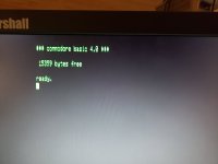
3) this is an 8032 so shouldn't it have 30k ram not 16?

I tried twice to write the pettester rom to two different 2716's (ST M2716-1F1) and both failed. I only ordered 5 so I'm not really wanting to just keep trying. I do have a UV eraser which I'll try on these failed ones but it's hit or miss whether or not it'll actually erase them.
 
Well, more steps forwards...

You are correct - an 8032 should have 32K of memory not 16K.

What BASIC is doing (on startup) is checking the amount of memory it has in a simple way. It is finding that the first byte it is testing in the second bank of 16K is not responding. It is then assuming that only 16K is fitted!

My PETTESTER will do the same thing - but there is a little 'trick' you can do to swap the two banks of 16K over. This will (of course) make BASIC fail (in your case) but my PETTESTER will go on to test it...

However, if you can't get the PETTESTER to work...

I wound't bother too much about the psychedelic 1960's characters just yet! This could still be a dicky IC, but it could be a capacitor in the monitor somewhere. As I said, I hate the 'funny' faults - so let's work on the things we know don't work for sure...

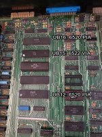
First question, do you have the PIA and VIA devices plugged in or not? And the keyboard connected? I know it sounds daft - but speaking from experience here!

Who's EPROM programmer are you using? The EPROM requires a 25V programming supply - but it does take a fair amount of current. Double check that the manual states it can provide a 25V programming pulse. Some EPROM programmers say they will program a 2716 - but not the 25V type! Also, if it has an option of either working from a USB cable or an external supply - make sure you are using the external supply. Most USB-powered programmers just fail to program these types of EPROMs...

Do you hear a 'chirp' on start-up?

Can you also check for the VERTICAL DRIVE signal on UB12 (6520 PIA) pin 18. The keyboard scanning is interrupt driven.

Can you also check for signs of signal activity on UC11 (74LS145) pins 12 through 15. This is the keyboard scanner.

Perhaps a short video of your character problems at some stage?

Dave
 
Last edited:
at first I didn't have the keyboard plugged in but after the initial boot I went and grabbed it, powered it off, plugged it in, and powered it back on.
I haven't taken any other chips out of the board so the PIAs and VIA are still there:
20221015_093600.jpg
 
There is no trick to writing the PETTESTER ROM at all.

Are you using the BIN or HEX file to download to the programmer? The BIN file should be exactly 2K Bytes (2048 bytes) in size.

What is your programmer and how do you know it is not programming correctly?

The usual "hit & miss" could be how you are actually programming the device itself (or more correctly, transferring the file down to the programmer).

Perhaps you could post the process you are using?

It would be way more useful to concentrate on getting this running. It is the only way to truly test the RAM - and makes testing the keyboard much easier.

Got to go and do some chores...

Dave
 
Back
Top