• Please review our updated Terms and Rules here

NOT WORKING CBM 3032

You have the same problem...

Should the signal be high or low?

Dave
Please Dave can you help me to solve this fault meanwhile i read some books?
This is my friend's pet and I wish I'd had it working before Christmas :(
In the meantime, I will also change the white sockets Rom because they seem worn to me.
 
i am desperate because i can't understand :(
To be fair 'Distance' learning can be extremely difficult at times and this whole subject of 'logic gates' etc can be very confusing, Maybe you are trying to achieve too much at once ?, Perhaps take a step back and take Dave's advice and gather read and digest information on how logic gates etc work, I don't know what your trade is in but most of my working life was in the garage trade, I started off in HGV repairs and moved onto Car repairs, Engine / Auto transmission rebuilds etc, Computers has been my hobby for many years and i'm certainly no electronics expert, I have a set of 'Introductory to digital techniques' manuals from 'Thorn' television circa 1977 > one of which is on logic gates, Even though they are meant to be 'introductory' and meant for 'Thorn' techs i find them confusing at first.
 
So no more repairs until you use one of your working PETs to learn some electronics... Happy to help with the learning so you are not on your own - but let's start a new thread for this.

In the meantime what devices are in sockets on this PET? Is the character generator (F10), latch (F9) or video RAM (F7/F8) in sockets or not?

I am suspecting that the problem is somewhere on schematic 
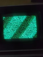
http://www.zimmers.net/anonftp/pub/cbm/schematics/computers/pet/2001N/320349-8.gif and associated with signal SD7 to/from F7 (because the character looks correct - it is just in inverse video). The question is "what is causing this"...

It can't be a 'hard' fault if sometimes the characters 'twinkle'.

With no 6502 CPU in we didn't have any 'twinkling' characters (implying the 'twinkle' is associated with the CPU access) but the screen was less-than-random to me.

When the NOP generator was in, what did you observe on the screen then? The CPU would have been reading from the screen RAM, but not writing to it, at this stage.

I am partially thinking of a 'slow' or 'noisy' gate or signal somewhere.

One possible test we could do (with the PETTESTER running) would be to connect F9 pin 12 (74LS373 Q5 = signal LSD7) to 0V/GND via a 100 Ohm (or so) resistor and see what we get then. This would 'kill' the inverse video characters, but it would be interesting to see if it fixes the non-inverse video characters.

Dave
 
Last edited:
So no more repairs until you use one of your working PETs to learn some electronics
Yes Dave, this evening I'm going to Milan to buy an old non-functioning pet from a boy. On that pet, if you want, I'll open a separate post and I'll use it to learn the basics of electronics, using the computer for practice!

In the meantime what devices are in sockets on this PET? Is the character generator (F10), latch (F9) or video RAM (F7/F8) in sockets or not?
At moment i have these ic in socket:

CPU
6522
6520
NE555
UD6, UD7, UD8, UD9, UF10
UA10
 
No faulty PET please. We need a working PET...

The expectation is that you will start to understand the CORRECT operation of the ICs. If you have a FAULTY PET, then what you could be looking at could be WRONG!

Can you please re-read post #83. I have edited it since you last posted.

Dave
 
One possible test we could do (with the PETTESTER running) would be to connect F9 pin 12 (74LS373 Q5 = signal LSD7) to 0V/GND via a 100 Ohm (or so) resistor and see what we get then. This would 'kill' the inverse video characters, but it would be interesting to see if it fixes the non-inverse video characters.
Ok thanks Dave! With or without Nop?
 
Dave with F9 pin12 to gnd i have this screen:
 

Attachments

  • 1670593364492..jpg
    1670593364492..jpg
    1.4 MB · Views: 11
That actually looks correct! So we are on the right track!

Check the display against the display in my PETTESTER documentation (with the exception that you will not have any inverse characters). Do they match?

OK, trusty oscilloscope out and remove the shorting link.

Measure the signal on F9 pin 12 with the oscilloscope (PETTESTER running of course).

The problem is, I don't know what we are looking for :) - so we will just have to see what you get.

When you put your oscilloscope probe on F9 pin 12 - look at the screen and see if the 'twinkles' either go way or change in some way.

This is really a qualitative measurement at this stage rather than a quantitive measurement.

Dave
 
When you put your oscilloscope probe on F9 pin 12 - look at the screen and see if the 'twinkles' either go way or change in some way.

No i have always same screen on Pet.
 

Attachments

  • 1670600070211..jpg
    1670600070211..jpg
    1.2 MB · Views: 5
I can't tell much from the oscilloscope screen photograph I am afraid.

Can you take a video of the following please:

1. The PET screen with the shorting resistor OFF and then ON (between F9 pin 12 and GND/0V).

2. The PET screen with the shorting resistor between E7 pin 11 and GND/0V.

3. The PET screen with the shorting resistor between E7 pin 8 and GND/0V.

4. The PET screen with the oscilloscope probe on F9 pin 12.

5. The PET screen with the oscilloscope probe on E7 pin 11.

6. The PET screen with the oscilloscope probe on E7 pin 8.

Dave
 
Last edited:
I think I have worked out the oscilloscope trigger to identify your problem...

Trigger the oscilloscope on the VDRIVE signal to the monitor and then use your other probe to look for positive-going pulses on F9 pin 12.

F9 pin 12 should be LOW for the first 128 characters then HIGH for the next 128 characters. The signal is clearly going HIGH when it shouldn't.

You need a STABLE picture on your oscilloscope screen of a couple of the problematic pulses observed on F9 pin 12.

You can then work backwards with your oscilloscope probe to E7 pin 8 and then back to E7 pin 11. We are looking for the pulse to go away...

This would indicate to us where the errant pulse was being generated at.

Dave
Good morning!
So need i put ch1 trigger probe on J7 pin3 and with ch2 probe on the others pins, right?
 
You have the entire video frame on the oscilloscope. Too much data is being displayed.

Speed up the timebase...

What I recommend you do is to trigger the scope on the VDRIVE signal (as you are doing) and measure the HDRIVE signal with the other probe. Get about 5 HDRIVE pulses on the screen after the initial VDRIVE pulse.

Leave the timebase alone and then measure the pins of interest from post #92.

Dave
 
I am desperate!
If i increase speed, i see this on hdrive pin but I can t see Vdrive...
 

Attachments

  • 1670674895231..jpg
    1670674895231..jpg
    1.3 MB · Views: 5
  • 1670674937640..jpg
    1670674937640..jpg
    1.4 MB · Views: 5
That's fine. All I am using the VDRIVE signal for is to lock the display so we can see what we are looking for. You don't always have to see the trigger waveform.

You may need to change the state of the SLOPE button, but we can look at that presently.

Dave
 
That's fine. All I am using the VDRIVE signal for is to lock the display so we can see what we are looking for. You don't always have to see the trigger waveform.

You may need to change the state of the SLOPE button, but we can look at that presently.

Dave
So what can i do now please?
 
Back
Top