• Please review our updated Terms and Rules here

PET 2001N IEEE-488 interface issue

razza

Member
Joined
Mar 4, 2024
Messages
42
Location
South-London
I bought an SD2PET a couple of weeks back and it's been fine for the few hours I have used it. When I execute CATALOG from the machine locks. If I use LOAD "$",8 it just searches. When the machine boots, the LED on the SD2PET is not illuminated. After the CATALOG command is executed, the LED goes green. I am assuming the SD2PET is functioning.

Daver2 shared a link to a book entitled PET and the IEEE 488 Bus (GPIB) by Fisher, E. R. (Eugene Ralph), 1940-; Jensen, C. W. (C. William), I have not yet looked at this.

I have read this thread Commodore PET restoration help needed and I have mostly replicated the testing found in post 144 which I think is taken from the table in the Tynemouth Blog. I have not tested the voltages on the IEEE interface yet.

For those who understand how this interface works, does anything look awry in the following results?

DIO1-8: Starting value 255
POKE 59426,0. PRINT PEEK(59424) value of 0.
POKE 59426,255. PRINT PEEK(59424) value 255.

EOI: Starting value 249
POKE 59409,52. PRINT PEEK(59408) value of 185.
POKE 59409,60. PRINT PEEK(59408) value 249.

DAV: Starting value 189
POKE 59427,52. PRINT PEEK(59456) value of 61.
POKE 59427,60, PRINT PEEK(59456) value of 189.

NFRD: Starting value 189
POKE 59456,253. PRINT PEEK(59456) value of 189.
POKE 59456,255. PRINT PEEK(59456) value 255.

NDAC: Starting value 255
POKE 59425,52. PRINT PEEK(59456) value of 254.
POKE 59425,60. PRINT PEEK(59456) value 255.

ATN: Starting value 60
POKE 59456,251. PRINT PEEK((59425) value of 188.
POKE 59456,255. PRINT PEEK((59425) value of 188.
 
Last edited:
ATN isn't working for a start!

If the PEEK value doesn't change between POKES, either you are entering some detail incorrect, or the pin is not working correctly.

Dave
 
I found similar problem with my PET and SD2PET. I got some errors when connected to the PET and finally was not able to dectect it. I send the SD2PET to a friend and it woked on his PET so, the problem was the PET, not the SD2PET.

The solution in my case was easy: Deeply clean the PET edge connector (even if they looks clean), first with contact cleaner and later with isopropylic alcohol. After doing this all worked like a charm. Good luck!
That is plausible, in that Gold plated edge connectors and other Gold plated connectors can get a clear glassy film that is an insulator. They can appear to the eye to be clean. The problem though normally crops up on touching Gold contacts rather than sliding ones. (offenders being DIP switches, Attenuators in Tek scopes, ZIF sockets etc) Still it cannot hurt to clean them, but don't use abrasive paper, the contact cleaner and noting more abrasive than A4 paper is fine.

The MC3446 interface IC's appear to have a fairly high failure rate. But this is characteristic of many IC's that interface directly with the "outside world". They are prone to being damaged by electrostatic discharges and other equipment with floating chassis that result in discharge currents when peripheral devices are connected. The same is true for IC's on parallel data links, or serial RS232 links.
 
Run the program from the Fisher & Jensen book. Just be careful keying it in, its easy to make an error.
Once I sort a way of saving what I type I will, that's my current task.

I found similar problem with my PET and SD2PET. I got some errors when connected to the PET and finally was not able to dectect it. I send the SD2PET to a friend and it woked on his PET so, the problem was the PET, not the SD2PET.

The solution in my case was easy: Deeply clean the PET edge connector (even if they looks clean), first with contact cleaner and later with isopropylic alcohol. After doing this all worked like a charm. Good luck!
The SD2PET didn't work that well when I first got it. I cleaned the edge connector with the pen end of an eraser until it was shiny, then isopropyl alcohol and finally a small squirt of Konakt10. I did try this again but no change :(

The MC3446 interface IC's appear to have a fairly high failure rate. But this is characteristic of many IC's that interface directly with the "outside world". They are prone to being damaged by electrostatic discharges and other equipment with floating chassis that result in discharge currents when peripheral devices are connected. The same is true for IC's on parallel data links, or serial RS232 links.
I am wondering if the joystick/cb2 adaptor I inserted has caused a problem. I was careful to hold the board by the sides. My gut feel is the 6522 based on this.

Things seem to change with heat. I tried it again and CATALOG worked after powering it on first time today. I tried to load a program and that failed. Not CATALOG fails (hangs) again.
 
Last edited:
The test with the PEEKs and POKEs should be done without anything plugged onto the IEEE488 port.

The test doesn't care about dirt or anything on the gold.

If the test does not work, it is the PET that is at fault.

When you get the test to work - then is the time to start cleaning up the gold etc.

Do your connectors have the correct key in them? If not, it is so easy to plug a PET edge connector in the wrong way around and potentially do damage.

Dave
 
Do your connectors have the correct key in them? If not, it is so easy to plug a PET edge connector in the wrong way around and potentially do damage.

Dave
On my connector assortment, they didn't have the key so I put TOP stickers on them to make sure I didn't forget and plug them on upside down ! It is a bit of a trap.
 
The test with the PEEKs and POKEs should be done without anything plugged onto the IEEE488 port.

The test doesn't care about dirt or anything on the gold.

If the test does not work, it is the PET that is at fault.

When you get the test to work - then is the time to start cleaning up the gold etc.

Do your connectors have the correct key in them? If not, it is so easy to plug a PET edge connector in the wrong way around and potentially do damage.

Dave
My connectors don't have keys but the SD2PET is pretty obvious which way up. It had not been unplugged until it failed, so no insertion errors.
 
Run the program from the Fisher & Jensen book. Just be careful keying it in, its easy to make an error.
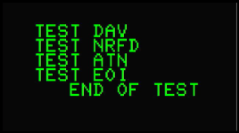
I got the C2N to play nicely. I typed the program in and checked it. All it does is show "END OF TEST", I'll go through it again tomorrow with fresh eyes.
 
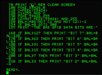
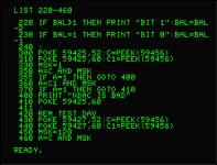
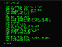
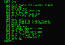
I can see no errors in my code taken from PET and the IEEE 488 Bus (GPIB) physical page 184. I then added (after the screen grabs below) PRINT statements at lines 421,521, 621 and 704 to show which IEEE488 lines were being tested. It never tests the data lines and the code returns nothing useful on the control lines:
1741503327303.png

My code taken via RGBtoHDMI screen grabs to ensure I introduce no errors:
1741503532791.png

1741503448636.png

1741503462635.png

1741503475924.png
 
I got the C2N to play nicely. I typed the program in and checked it. All it does is show "END OF TEST", I'll go through it again tomorrow with fresh eyes.
Yes that annoyed me too.

I modified the code to actually say that all was ok for each test. Otherwise if you see that result for the first time, it leaves you wondering if everything was ok or not. When its not it reports the error, but the thing is when all is ok you don't know that unless you study the program.
 
>>> It never tests the data lines

What do you think the lines from 100 to 230 do?

>>> and the code returns nothing useful on the control lines

The program tells you when the control line test has failed.

It is then up to you to read the associated chapter of the book, manually use the PEEK and POKE commands (as you have done in an earlier post) in conjunction with a multimeter to measure the voltages from the output pin of the PIA through to the bus connection and back again to the input pin of the PIA to ascertain whether it is the PIA that is at fault or a particular bus buffer.

If the test program gives you a clean bill of health, but we had a faulty ATN signal when you tested it manually, do you still get a fault now or not (if you use the same POKE and PEEK commands as previously)?

Dave
 
>>> It never tests the data lines

What do you think the lines from 100 to 230 do?
I didn't read the code, I just typed it and checked syntax. I can see it skips that section as it got a good result (line 154).

>>> and the code returns nothing useful on the control lines

The program tells you when the control line test has failed.
See next comment...

Yes that annoyed me too.

I modified the code to actually say that all was ok for each test. Otherwise if you see that result for the first time, it leaves you wondering if everything was ok or not. When its not it reports the error, but the thing is when all is ok you don't know that unless you study the program.
Agree annoying, it's a few PRINT lines to make it more usable. I'll modify that at some point.
 
Last edited:
I got bored with typing PEEK and POKE statements which also allows room for error. I wrote this for consistency (and error checking on my part)...
Code:
10 PRINT "CLS" : REM CLS TO BE REPLACED WITH <SHIFT-CLR/HOME>
20 PRINT "IEEE-488 PEEK POKE TEST": PRINT ""
30 PRINT "DI01-8 TEST"
40 A=PEEK(59424):A$=STR$(A)
50 POKE 59426,0
60 B=PEEK(59424):B$=STR$(B)
70 POKE 59426,255
80 C=PEEK(59424):C$=STR$(C)
90 PRINT "INIT=" + A$ + ", P LOW= " + B$ + ", P HIGH=" + C$ : PRINT ""
100 PRINT "EIO TEST"
110 A=PEEK(59408):A$=STR$(A)
120 POKE 59409,52
130 B=PEEK(59408):B$=STR$(B)
140 POKE 59409,60
150 C=PEEK(59408):C$=STR$(C)
160 PRINT "INIT=" + A$ + ", P LOW= " + B$ + ", P HIGH=" + C$ : PRINT ""
200 PRINT "DAV TEST"
210 A=PEEK(59456):A$=STR$(A)
220 POKE 59427,52
230 B=PEEK(59456): B$=STR$(B)
240 POKE 59427,60
250 C=PEEK (59456):C$=STR$(C)
260 PRINT "INIT=" + A$ + ", P LOW= " + B$ + ", P HIGH=" + C$ : PRINT ""
300 PRINT "NFRD TEST"
310 A PEEK(59456):A$=STR$(A)
320 POKE 59456,253
330 B=PEEK(59456):B$=STR$(B)
340 POKE 59456,255
350 C=PEEK(59456):C$=STR(C)
360 PRINT "INIT=" + A$ + ", P LOW= " + B$ + ", P HIGH=" + C$ : PRINT ""
400 PRINT "NDAC TEST"
410 A=PEEK(59456):A$=STR$(A)
420 POKE 59425,52
430 B=PEEK(59456):B$=STR$(B)
440 POKE 59425,60
450 C=PEEK(59456):C$=STR$(C)
460 PRINT "INIT=" + A$ + ", P LOW= " + B$ + ", P HIGH=" + C$ : PRINT ""
500 PRINT "ATN TEST"
510 A=PEEK(59425):A$=STR$(A)
520 POKE 59456,251
530 B=PEEK(59425):B$=STR$(B)
540 POKE 59456,255
550 C=PEEK(59425):C$=STR$(C)
560 PRINT "INIT=" + A$ + ", P LOW= " + B$ + ", P HIGH=" + C$ : PRINT ""
 
..... we had a faulty ATN signal when you tested it manually, do you still get a fault now or not (if you use the same POKE and PEEK commands as previously)?
Yes, it seems that way. In the following table, INIT = Initial value, P LOW is the value after poking low. P HIGH after poking high.

DI01-8 TEST
INIT= 255, P LOW= 0, P HIGH= 255

EIO TEST
INIT= 233, P LOW= 169, P HIGH= 233

DAV TEST
INIT= 189, P LOW= 61, P HIGH= 157

NFRD TEST
INIT= 189, P LOW= 189, P HIGH= 255

NDAC TEST
INIT= 255, P LOW= 254, P HIGH= 255

ATN TEST
INIT= 60, P LOW= 188, P HIGH= 188
 
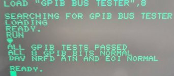
I modified the program to report the attached (makes me feel better)

I just had an interesting experience with my SD2PET that has not happened before. The computer could not find it. I have not used it for a while. After plugging it in and out a few times it started working. All the connections appeared perfectly clean, though it must have been a bad connection. It goes to show it does pay to clean the connectors from time to time.
 

Attachments

  • GPIB.jpg
    GPIB.jpg
    66.3 KB · Views: 10
Notice that you have missed a POKE command out from your test program as opposed to the one in the book.

Driving ATN is directly from the POKE.

The ATN input is not a direct PEEK. It is a bit more convoluted.

This is probably why the book program is working, but your test program is not.

Dave
 
1741558680852.png
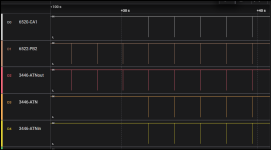
I have not had time to read the datasheet or the book in detail on ATN behaviour. My program has two identical FOR..NEXT loops creating a pause between driving the ATN line high then low. To the untrained eye, I expected to see a symmetrical square wave on D3.

I am also lost as to why D0 took numerous cycles of my program to strat working.

I'll have to read a bit more when I get time.

Thanks for your help so far.
 
Back
Top