• Please review our updated Terms and Rules here

The Sol Prototype Project

You are still "Hand Holding" the routing ... that's not a whole lot different than trying to cut a piece of paper with lines one it using hand scissors. You can be close, but a CNC is exact.

Uhm... no? The video describes using bearing bits that have a wheel bearing that follows the template piece. All you need to is just make sure the bearing keeps in firm contact with the template as you steer the wood past the bit. The bearing wheel prevents you from being able to cut too deeply into the piece, so as long as you don't let the work piece wander *away* from the bit you'll end up with an exact copy.

I mean, sure, not going to deny that a CNC table is great and all, but if you don't have access to one a hand router is a lot cheaper...
 

Hi,

The side panel files are just profiles, not 3D models. I make 3D models in SolidWorks to have a full definition to recreate the parts, but still, IF I use a modern USB keyboard (I don't want to build a sponge keyboard) the width of the cabinet could be wider for standard modern USB keyboards, or maybe the same width with a 72-84 key USB keyboard.

Before getting into any of the final 3D model design, I need the main board to know how it will fit along with using Mean-Well switching power supplies. It all comes down to getting the main board first.

.
 
FWIW, the linked replica uses cherry (or clone) keyswitches, not the original Keytronic foam. They're what's in most "mechanical" USB keyboards these days.

Hi,

It's still easier and a lot cheaper to just drop in a modern USB keyboard with a USB keyboard to Parallel ASCII adapter. That's my plan if I can get a reproduction Sol-20 main board.


.
 
It's still easier and a lot cheaper to just drop in a modern USB keyboard with a USB keyboard to Parallel ASCII adapter.

Seems like a kind of odd hill to die on if you’re spending all the money and effort on the PCB, vintage components to populate it, fabricating the case, paint, decals… all to ruin it with an obviously modern keyboard nested on top?
 
The reason I choose to do the case first is because it provides motivation. I find I have so many projects on the go that I often forget or get demotivated. I built the case for my TVT first, and I placed it on my desk and it confronted me there every day for 2 years. And I really think that helped me get the job done.

Just based on Lee's comments alone I'm not confident this will work. It may well end up being a static display piece. And I'm good with that. But I want it to look decent.

Speaking of which.. my technique, such as it is, is kind of borrowed from my model railroading. I deduce what I can in the way of measurements from the available photos (I really don't think CHM would let me turn the real prototype sideways, tracing pencil around it or taking it completely apart), then I build my model. Then I stage photos of the model to try and match the angle the original photos were taken to try and get the right look. If by my eye it looks right, that's good enough. It's kind of a challenge.. maybe one day I take my replica down to CHM and put it beside the original and see how close I got.

Right now I kind of suck at 3d CAD. I do need to learn that.

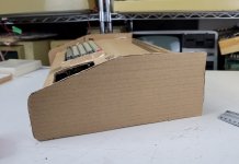
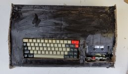
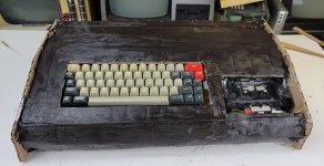
Anyway here are some photos of the cardboard mockup with some hastily applied black acrylic paint. I think I'm getting there.20221026_200014.jpg
 

Attachments

  • 20221026_203725.jpg
    20221026_203725.jpg
    348.9 KB · Views: 5
  • 20221026_203932.jpg
    20221026_203932.jpg
    352.2 KB · Views: 5
Last edited:
At least the sides are done for you:

https://github.com/osiweb/Hardware/tree/master/new/sol20/sides

Note that the edges are routed with a 1/4" radius bit on both sides to give the rounded edge. Will the CNC mill do this for you or produce a straight cut side only?
As for the prototype, well it was clearly taken apart for the Bitsavers photos. But no ruler, scale, graph paper or round coin was placed alongside. Museums these days, really :)
 
Last edited:
Seems like a kind of odd hill to die on if you’re spending all the money and effort on the PCB, vintage components to populate it, fabricating the case, paint, decals… all to ruin it with an obviously modern keyboard nested on top?

Hi,

Having a reproduction main board, other reproduction or original S-100 boards (I have all five for a Subsystem B already) will make a functional Sol-20 Terminal Computer. The keyboard doesn't need to look exactly like an original Sol-20 keyboard, it just needs to function. IF I wanted an original Sol-20, then I'd just buy one, but my interest is having a functional Sol-20 Terminal Computer.

I haven't tried them all, but I am finding that some of the emulated computers on Raspberry Pi or Arduinos or Beagles do not function exactly correct, so building a functional Sol-20 Terminal Computer is a project I'd like to get into once a good tested reproduction main board is availble.

.
 
I haven't tried them all, but I am finding that some of the emulated computers on Raspberry Pi or Arduinos or Beagles do not function exactly correct, so building a functional Sol-20 Terminal Computer is a project I'd like to get into once a good tested reproduction main board is availble.
Have you ever stopped to ask what that might be? After all, the emulator host boasts thousands of cycles to a single SOL CPU cycle. At that scale, anything should be possible.
 
The side panel files are just profiles, not 3D models. I make 3D models in SolidWorks to have a full definition to recreate the parts, but still, IF I use a modern USB keyboard (I don't want to build a sponge keyboard) the width of the cabinet could be wider for standard modern USB keyboards, or maybe the same width with a 72-84 key USB keyboard.
They are more than just profiles. The vcarve files contain tool specifications and depths, which you can use with an actual CNC mill. (You may need to modify the tools and feeds/speeds to match your own CNC setup, but that's a reality of any CNC). That's all you need to fabricate. A 3D model is useful when you want to render the entire assembly, but doesn't add anything if you are making the panels out of wood. If you want 3D models, you can certainly start with the DXF outlines and extrude the wood and holes to the proper depths, and add the roundover along the edges. The measurements were taken from the original sides using a special jig.
 
Note that the edges are routed with a 1/4" radius bit on both sides to give the rounded edge. Will the CNC mill do this for you or produce a straight cut side only?
The CNC can do roundovers, but getting both sides would be tricky. It's much easier to CNC a square edge and use a hand router or router table (if you have access to one) to round over the edges. And of course, you can always just print the files and use them to laser cut a template, then use a hand router to

Regardless, the difference between an OK result and a great result has nothing to do with the CNC. You can get a great result with hand tools only using the design as a template. It's the sanding and finishing that makes the difference.
 
Last edited:
Hi,

I'm not talking about speed, I'm talking about math errors and other functions not working correctly.

Have you ever stopped to ask what that might be? After all, the emulator host boasts thousands of cycles to a single SOL CPU cycle. At that scale, anything should be possible.
 
The CNC can do roundovers, but getting both sides would be tricky. It's much easier to CNC a square edge and use a hand router or router table (if you have access to one) to round over the edges.

Hi,

A CNC mill can mill the entire piece using a simple reference on the part to the machine.


.
 
My point is that, given the huge advantage of a later CPU, that nearly 100% accurate emulation should be possible. Anything less would seem to be sloppy coding.

So wouldn't it be simpler to code the emulation yourself rather than embark on an attempt to recreate the original?
 
A CNC mill can mill the entire piece using a simple reference on the part to the machine.
The fact that something is possible doesn't always make it a great idea. Unless you build a jig, you risk imperfect alignment on the flip, which will ruin the appearance. This is done when both sides need to be machined, but for rounding over the edge, it's much easier and more reliable to do the roundover by hand. Faster as well.
 
As for the prototype, well it was clearly taken apart for the Bitsavers photos. But no ruler, scale, graph paper or round coin was placed alongside. Museums these days, really :)
CHM was kind enough to do that for me personally when I asked.. they did it either just before or just after Al took his pictures. Here's an example: https://drive.google.com/file/d/1cIDV3BKN1ZvXo2JD_4InCzO0qF7Z93dr/view?usp=sharing

These helped - although because of placement and camera angle it's hard to tell in some pics what the accurate measurement is. I was just grateful CHM was willing to do this at all, so I didn't press my luck and ask them to retake any photos or actually take measurements. In cases where it wasn't clear, what I've done is use my tablet, and scale the thing up to full size so that I have a part of the prototype scaled to a known dimension, and then I extrapolate from there. But even then sometimes I have to kind of trim things by eye and do a bit of guesswork. That's why I've gone with building a model from box. It won't be to the millimeter accurate but I think it'll be close enough.
 
Having a reproduction main board, other reproduction or original S-100 boards (I have all five for a Subsystem B already) will make a functional Sol-20 Terminal Computer. The keyboard doesn't need to look exactly like an original Sol-20 keyboard, it just needs to function. IF I wanted an original Sol-20, then I'd just buy one, but my interest is having a functional Sol-20 Terminal Computer.

Are we defining "Sol-20 Terminal Computer" as the prototype that @falter is trying to recreate, or a "shipping" SOL computer configured in the minimal "basically just a terminal" configuration? (Which so far as I understand would actually be a "SOL-PC" or "SOL-10" configuration with the minimal CONSOL personality module/ROM.) Because if it's the latter... couldn't you just effectively run CONSOL on your Subsystem B? Essentially all the main (shipping) SOL mainboard is is a 3P+S I/O, VDM-1 video, CUTS tape system, and GPM ROM/RAM board stuffed onto one PCB (along with an 8080)? Poking around the main difference between CUTER and SOLOS is CUTER lacks the stand-alone terminal emulation, but... is there any hardware reason why you couldn't swap the CUTER ROM for the actual SOL-20 versions of SOLOS and/or CONSOL?
 
The fact that something is possible doesn't always make it a great idea. Unless you build a jig, you risk imperfect alignment on the flip, which will ruin the appearance. This is done when both sides need to be machined, but for rounding over the edge, it's much easier and more reliable to do the roundover by hand. Faster as well.

Hi, Or use three specific points of reference on both sides of the board ... very easy to make.

.
 
Are we defining "Sol-20 Terminal Computer" as the prototype that @falter is trying to recreate, or a "shipping" SOL computer configured in the minimal "basically just a terminal" configuration? (Which so far as I understand would actually be a "SOL-PC" or "SOL-10" configuration with the minimal CONSOL personality module/ROM.) Because if it's the latter... couldn't you just effectively run CONSOL on your Subsystem B? Essentially all the main (shipping) SOL mainboard is is a 3P+S I/O, VDM-1 video, CUTS tape system, and GPM ROM/RAM board stuffed onto one PCB (along with an 8080)? Poking around the main difference between CUTER and SOLOS is CUTER lacks the stand-alone terminal emulation, but... is there any hardware reason why you couldn't swap the CUTER ROM for the actual SOL-20 versions of SOLOS and/or CONSOL?

Hi,

With a real Sol-20 Terminal Computer main board (the kits that shipped out to many of us back in the day) we can then make our own "Personality Modules", connect to RS-232 to PC terminals to send/receive programs or use a cassette I/O or other PROMs with programs.

It is a reproduction main board is the first thing needed to start making a Sol-20 Terminal Computer. From there each builder can build the machine they want be it hand made keyboard or like I just want to use a USB keyboard. I do have a couple of Processor Technology MCM6574P keyboard chips just in case.

.
 
Back
Top