• Please review our updated Terms and Rules here

Four-Phase Systems IV/90

I have a faint recollection that the bottom surface contain the servo-tracks, if so it becomes even more challenging, but it would also mean that it might be possible to recover all the data.

My own recollection and figure 3-17 in the reference manual suggests that it's the top surface of the middle disk that contains servo tracks:


The scratches that you saw - are they on the very bottom disk, or on disk 4-of-5 from the top? Because only the middle 3 disks contain data/servo.

Anyway, the work of Chris Fenton is interesting in case we'd ever have to archive a disk pack but we're unable to properly spin up the drive (the lack of servo could be one such reason):

 
Yeah I remember reading on his adventures back in the day to read that pack without the correct controller to run the drive. I have myself wondered how one would still retrieve the contents of a crashed pack by preventing one or more heads from loading but assuming it's not a servo track you have lost you would lose any date on the remainder of that surface.
 
During VCF MidWest I was gifted a set of five more boards from an IV/70 chassis. There was another Driver/Receiver and Normal Intensity character generator board (so I think that technically brings me up to 24 terminals I can attach) but there was also a variant of the DT board I already have (different part number and slightly different component arrangement) which may actually be very good, because we still have the unconfirmed report that the DT board is reworked when the system is upgraded to IV/90, so if this is an original IV/70 configured board, for testing purposes that would let me run with that whole expansion cabinet omitted.

11003104-52-fr_s.JPG


The big item however was the memory parity board.

11002712-A-fr_s.JPG

This is missing in my system but is required for the system to run, this means we are now just missing the two I/O interface boards that would sit next to this. Note the RAM 9 chips are remarked. They were originally P/N 91100091 but have been relabeled as P/N 91100101. No idea why. Perhaps these were tested with tighter margins and this deemed more suitable for parity control?

There is also another board that says its a synchronous communications adapter. I cannot cleanly tell if this was a single board or part of a multi board set like my other comm board.

11016431-A-fr_s.JPG


Board photos have been sent off to bitsavers for upload. I've added the chip part numbers to my running catalog. They will need to be recapped as they all contain those annoying 50uf 50v Sprague capacitors that seemingly are all either completely open or want to short soon after.
 
Last edited:
A terminal has been located.

I noticed another Four-Phase keyboard appeared on ebay (I know for a fact that I have saved searches and notifications setup and I am *not* getting notifications on these listings so I am guessing I'm missing out on scrap lot listings that are going up and almost instantly selling) and decided to inquire with the seller if they perhaps still had the terminal half. They did! It ended up costing me something like $200usd for the keyboard and terminal as-is and this is a VERY steep price but after two years of looking this is the first complete terminal I've seen for sale it was time to commit a bit more into making this work. The downside is it will have to take The Pony Express to make it from Wisconsin back to BC, so it may take a few weeks to a few months before it arrives. In the meantime, schematics for the keyboard, analog board + PSU and the digital board are already on bitsavers.
In the meantime as I've looked over the schematics I've realized that the terminal is mostly just composite video. The back of the IV/70 assumes one terminal per socket (and they are all Winchester plugs, so yay! money!) but you can if you want daisy chain up to four terminals, which uses interlaced video multiplexing. The keyboard needs Data_0, clock and sync but the video portion just needs VIDEO. Not even a balanced signal. Just analog video, accessible from up to 2000 feet away.
In theory, if you do not daisy chain terminals you do not need the CRT portion if the schematics read right because all the smarts in there are for demultiplexing and blanking the video signal when multiple terminals are in the chain. You just need the keyboard and you can make your pick of a video monitor with composite sync.
when the monitor arrives I'll be ready to take more photos, deal with its nasty cataract and do the other preventative maintenance. I have I/O boards dispatched on loan which if the planets align will get the system into a basic state. We're still a long way from saying it's alive but we are absolutely in a better place right now than we were at the beginning of the year. Hardware donations are still welcome btw.

While discussing disk packs for the system we are still running into issues confirming exactly what 8231 packs it wants. Diablo 30 drives came in various sector sizes, but many were hard-sectored. Looking at the filesystem arrangement in the Bitsavers book on peripheral programming it is alluded that it expects 8-sector packs. These in comparison to the 12 and 16 sector packs that DEC loved to use are nowhere near as common. If I ever do source an 8230 controller this still puts the disk drives on ice if a pack or multiple packs are unobtanium. It may become preferred instead to look into virtual disk emulation. I wonder how the RK05 emulator project has been going.....
 
Last edited:
Some 48 capacitors will need to be replaced. Just about every Sprague 50uf 50V was either leaky or bad. Everything else tested okay for capacitance and ESR.
There's an LM319N that got crunched that needs to be swapped. Currently DigiKey isn't playing nice with me for that.
There's one diode that got crunched but is somehow still good, but the part number is missing. At least I can measure what it's doing right now.
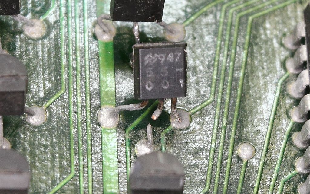
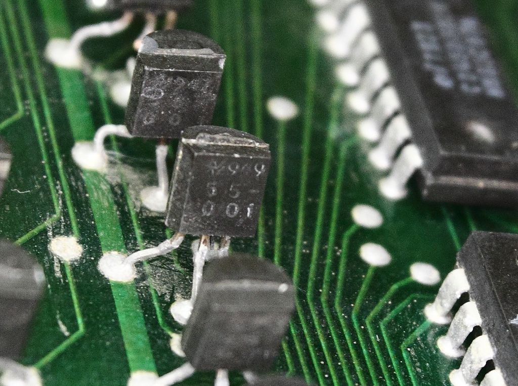
Lastly for missing board parts I got a transistor that was ripped off. It was in a group with other transistors or components in a similar package and with similar markings but I can't narrow down what the part actually is.

94755-001 or 94955-001. both were made by National Semiconductor.

CGS_11674.JPG

CGS_11675.JPG

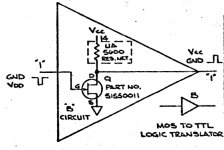
Returning to this mystery some two years later, while looking over the schematics for I/O interface card 1 (90012813-07) I noticed they too have a similar arrangement of resistor networks, 7438 buffers and a JFET. To simplify them on the schematic they mark them as a triangle with a B, then refer to both a diagram and a map of where similar circuits are located on the schematic.

5155.jpg

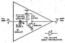
It still does not confirm for me what the real number for the part is but it tells me that the full house part number is 51550011 and it's being used for a MOS to TTL level converter, plus that the chinesium tester did correctly identify it.
I still have not checked what else may of been hurt with that Driver/Receiver card being placed into the memory parity board slot but now we know why so many parts were overdriving or blowing themselves apart. I still need to source replacements for the 2N3644 and 2N3643's that are probably bad. I looked into it back when that was an issue and never got back to researching. At least it seems the only casualties was the level converters and buffers rather than the larger four-phase IC's.

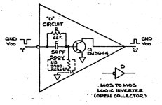
Edited: posting their diagrams for a logic inverter and a logic translator because what's weird is that in the translator they are using an RL50 LED as a part of the overall design, which is weird because it's doing a lot more than just acting like a diode.

LI.jpgLT.jpg
 
Last edited:
Sure--like the neon lamp in some vacuum tube circuits, an LED provides a relatively stable voltage reference. In the case above, it's dropping the input pulse by a prescribed level.
 
The last major boards have now arrived on loan. The two missing I/O interface boards.

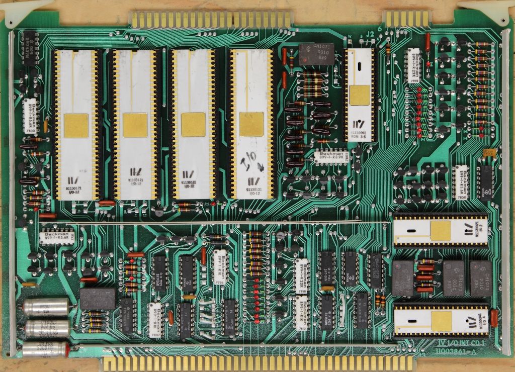
f8a75fcb-991c-4b5b-9774-b3ec8c10ae23.jpg

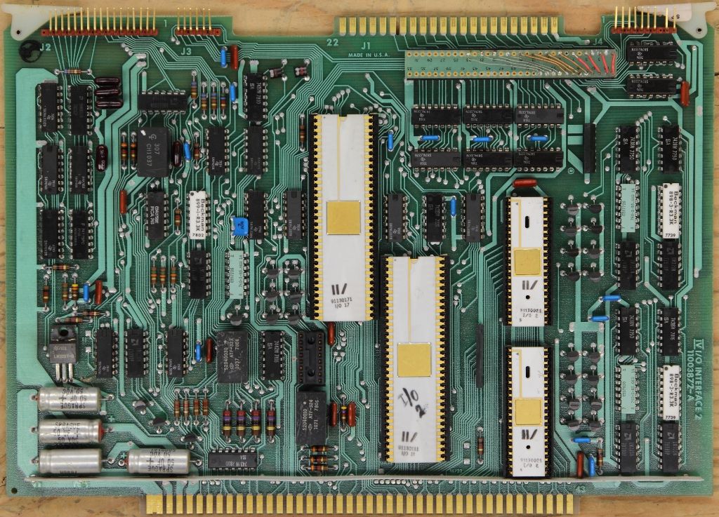
fbafa787-6aa7-4b91-9495-3b71253f1703.jpg


These two boards are the glue that hold the entire system together. Signals from the front panel, the DT, the CPU and the character generator boards all pass through here and nothing works without these. They have been photographed and sent off to Bitsavers, so we now have images of what a complete boardset looks like.
I also received on loan additional cabling that links these two boards to the distribution board and handled the video and keyboard I/O. We do not have wiring diagrams for these so I'll probably make new ones so that it's possible to make more in the future and return these ones. Both boards also have more of those 50v 50uf capacitors so they too need to be replaced. I'm hoping to complete a lot of the preventative maintenance and wiring work by next week and then it's finally time to see if we get life out of the front panel.
Note the DIP jumper headers. I do have *some* of the information on these. These are mainly for configuring the amount of ram, number of printers and other finer details. I have not gone through any of those yet.
 
falling behind on this....

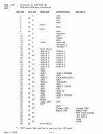
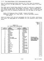
I have completed writing new wiring diagrams for the I/O interconnect cables but have not been able to find the several hours worth of time it will take to build the replacement cables. They require a bit of hackyness because I still cannot source the correct cable shrouds to contend with the top lid.....which in other OTHER news I am absolutely astounded post-COVID how you can walk into a metal shop asking to bend a piece of metal and they will not do it, even if you have cash in hand. I am astounded how goddamn hard it's been to make a lid.

In other news, I've discovered that Winchester and Gorn had different types of very similar connectors. Same number of pins. Same spacing. Pretty much same everything but the pins themselves are smaller, resulting in connectors that fit but don't actually connect.
Well that was a waste of $55.
 
In other news, I've discovered that Winchester and Gorn had different types of very similar connectors. Same number of pins. Same spacing. Pretty much same everything but the pins themselves are smaller, resulting in connectors that fit but don't actually connect.
Are these similar to the Winchester MRAC or MRE series of connectors? Even Winchester has different pin sizes, and even a half-sized connector that looks like MRAC in a photo but is shrunk by half!

If you need to make the pin side of the connector then it's possible to duplicate one using a PCB, individual pins, and a 3D printed shim. Making the socket side of the connector is difficult.
 
That's more or less my plan for the Diablo drives and yes it seems to be MRAC/MRE family. It's too expensive to source connectors, cabling and terminators for the drives but recently the RK05 project released PSB replacements for all of the above. At this point I'm considering the same for the terminal ports so a 15 pin Winchester connector can be converted to DB15 or HD15.
 
astounded post-COVID how you can walk into a metal shop asking to bend a piece of metal and they will not do it, even if you have cash in hand.
and people wonder why everyone buys from China.
Companies in general don't want to deal with one-offs coming off the street.
I have no idea where to go to have a piece of sheet metal cut and bent in Silicon Valley any more.
The only small shops I know around here are just doing CNC machining on contract.
Maybe a hacker space, if there are any left here.
I ran into someone who has gotten into machining his own tools, and he gets time at a junior college shop.
 
So after about five months the terminal has arrived for pickup in Seattle. I'll go retrieve it next weekend during the Interim Computer Festival.
The next is that after picking he brain of a few folks on the classicCMP discord we were able to narrow down on the printer that Four-Phase was selling and is seen in a lot of their marketing material. Really it should of been obvious but it's a Diablo, more specifically the HyType I and II models. The manual for these printers is available on Bitsavers. The printer did not attach to the terminal because remember, the terminal had no character generation circuit and was more or less a composite monitor. The printer regardless of where the terminal was would have to be connected directly to the computer. With that in mind I went back into the schematics and located the basic diagrams and strapping info for the line printer card. A very simple card with not much on it and which I had living in one of my I/O slots with nasty sunburn.
Interestingly, while the default HyType documentation makes no mention of it as an option, the line printer controller can be configured for either a single-ended 8-bit data bus or a differential 8-bit data bus. Presumably the idea here is that like the terminals which may not be in the same room as the computer, you can run the printer more than 25 feet away from the system. The pinout is also useful in figuring out how the heck this attaches to the funky 25 pin interface the HyType uses. Weather or not this can be adapted to a more conventional parallel printer interface I've yet to really sit down and check.

As for printers in 2025, HyTypes suck. I can only assume that Diablo loved the Winchester connector because both the data interface AND the power supply used them, so they were not just keeping this stupid connector exclusive to their drives. >:T
The printer themselves are of no surprise, not something littering ebay or other people's collections but it may be advisable much like with owning one complete terminal to also locate one printer as well, so lets add another item to the wish list. Interestingly right now there's someone buried away on Facebook selling a dozen of the later Xerox/.Diablo 630 printers with the late Motorola/Four-Phase badging. These would of likely been for the later 68K era of machines which I have no information about. I've fired off a message to inquire and to see if the same 50 pin interface lived on in the later products (and would then likely make this work with the older IV family) but being a printer, it's still incredibly heavy.

Edited: and yes the docs for the 630 are also on bitsavers. They move the pinouts near the back of the maintenance manual but the parallel variant of the printer is indeed backwards compatible and can be identified with a 50 pin Centronics connector.

Capture.JPGCapture630.jpgCaptureHSII.jpg
 
Last edited:
I used a Hytype I for several years in the 1970s. I recall that the power supply was an external box with at least 2 fans in it and was somewhat noisy. The interface was the OEM 12-bit interface with no smarts at all--you told the printer where to spin the wheel, told it to hit the hammer and then how much to move the carriage. My setup was driven by an S100 parallel (I think 2P+S, but am not sure) connected via ribbon cable. I may even be able to locate the driver I wrote for it (bidirectional, smart seeking).

The thing was a tank, weight-wise and pretty noisy.
 
That tracks. I've witnessed the early Diablo printers before but because of their extreme weight never had a reason to ever want one. The power supply......well it seems kinda par for the course from Diablo, especially since it wants 15v much like their disk drives.

Edited: UGH, oh god, so at least one point in the late 70's they also made some sort of an adapter to attach a serial (and very likely still a Diablo) printer to a terminal daisy chain. As I had found earlier the terminals are all more or less video devices straight out of the computer so this mysterious adapter (to which no schematics or other reference seem to of been found yet) converts the analog video signal back to a string of text in a serial format for the printer.Capture3.JPG
 
Last edited:
Interestingly right now there's someone buried away on Facebook selling a dozen of the later Xerox/.Diablo 630 printers with the late Motorola/Four-Phase badging. These would of likely been for the later 68K era of machines which I have no information about. I've fired off a message to inquire and to see if the same 50 pin interface lived on in the later products (and would then likely make this work with the older IV family) but being a printer, it's still incredibly heavy.
Man, that one pisses me off.
So it turns out those printers were not only special to four-phase they had the undocumented terminal passthrough and not the Line Printer interface, so they were indeed very very special and very much designed for my system.
I negotiated with the seller who by then was going on three weeks with no interest and wanted to get rid of them pretty quickly, I negotiated a deal for one shipped as-is because it's already in the carton, got the shipping quote, agreed on a $50 price and then it turns out they didn't have Paypal. Just Venmo and Zelle. Neither of these are available to anyone outside of the United States and after frantically asking around for SOMEONE on the west coast to close on the deal he got fed up with my BS and stopped talking, so I still don't have a printer. :C

Edited: adding photos form the Facebook listing and DM's.
Like, Brandon if you are reading this there's no hard feelings but I'm throwing money at my monitor and I got nothing that's compatible with your payment methods unless you want something obnoxious like a wire transfer or a money order.
 

Attachments

  • 482532368_1363014478453644_8235783192192528050_n.jpg
    482532368_1363014478453644_8235783192192528050_n.jpg
    136.6 KB · Views: 4
  • 483536338_650186337603501_1496956811764026664_n.jpg
    483536338_650186337603501_1496956811764026664_n.jpg
    151.4 KB · Views: 6
  • 483364602_4114584942153320_2490270337643393953_n.jpg
    483364602_4114584942153320_2490270337643393953_n.jpg
    142.5 KB · Views: 6
  • 482836663_1292942861998397_7844501712404470565_n.jpg
    482836663_1292942861998397_7844501712404470565_n.jpg
    100.5 KB · Views: 4
Last edited:
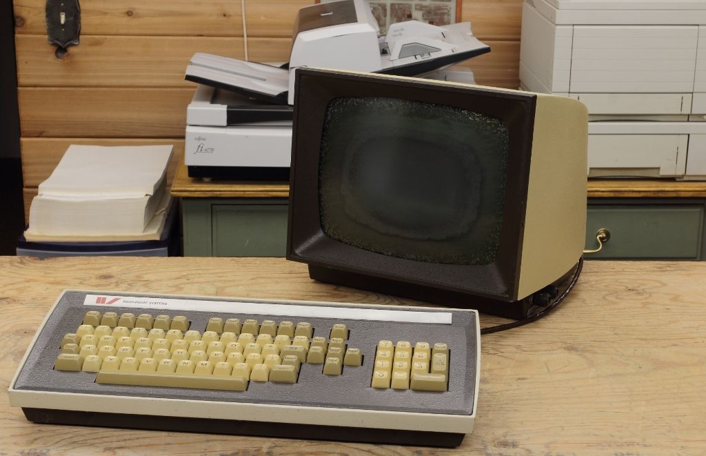
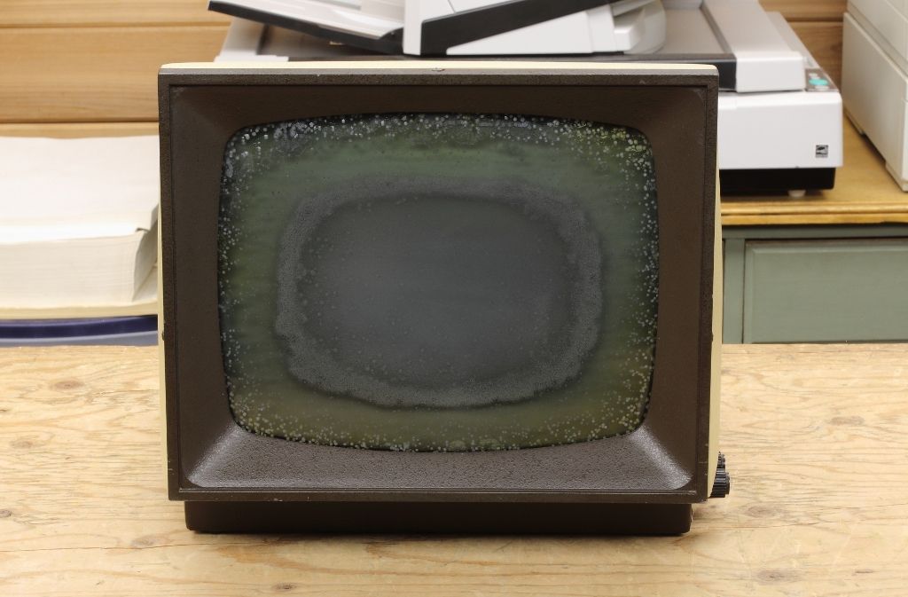
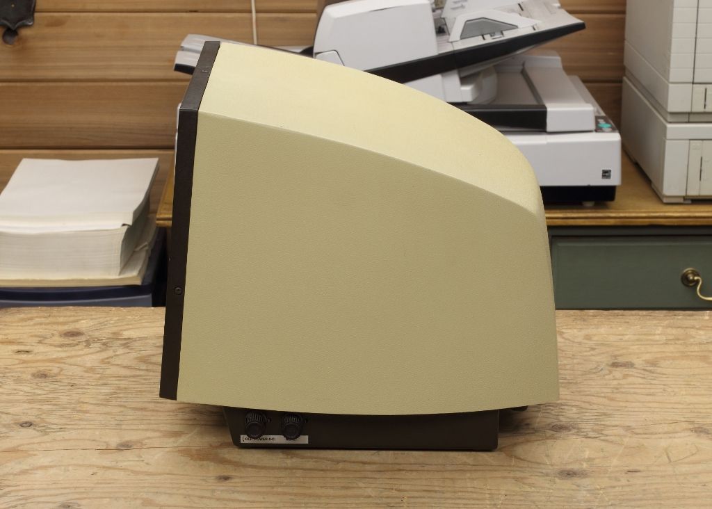
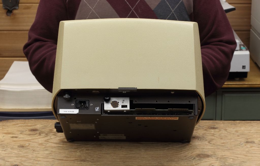
Folks we have a terminal.

bc7181ad-45a0-4f6b-97c8-4a62aba36332.jpg

2aa18d7b-22d4-4157-a756-ce6b8f08dd40.jpg

c13055a5-c93e-4359-8b70-9270da2196aa.jpg

60c8db67-d31b-440c-80fd-84d8fda8d919.jpg


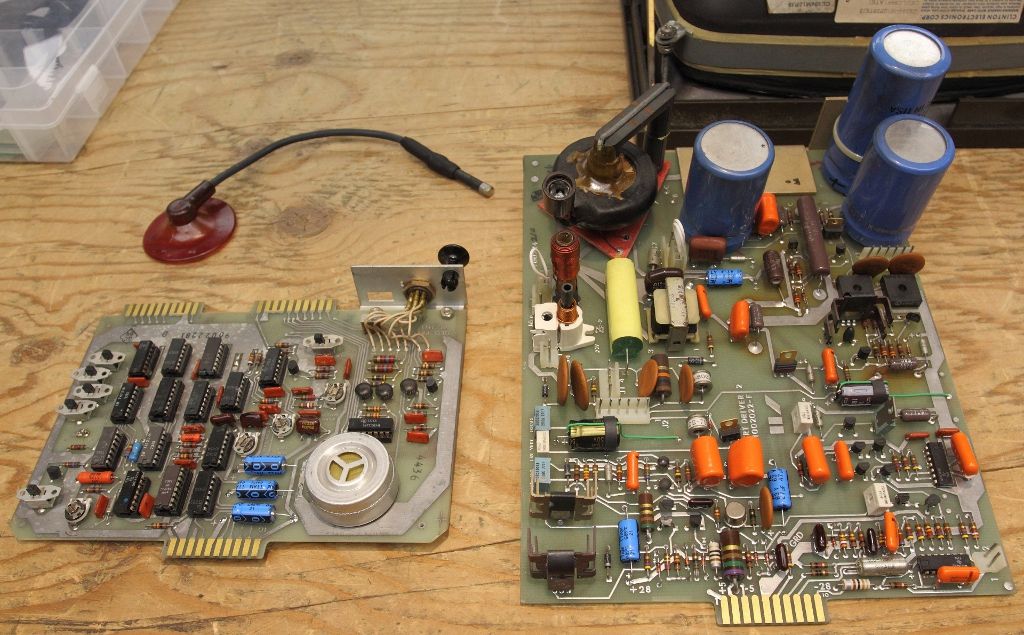
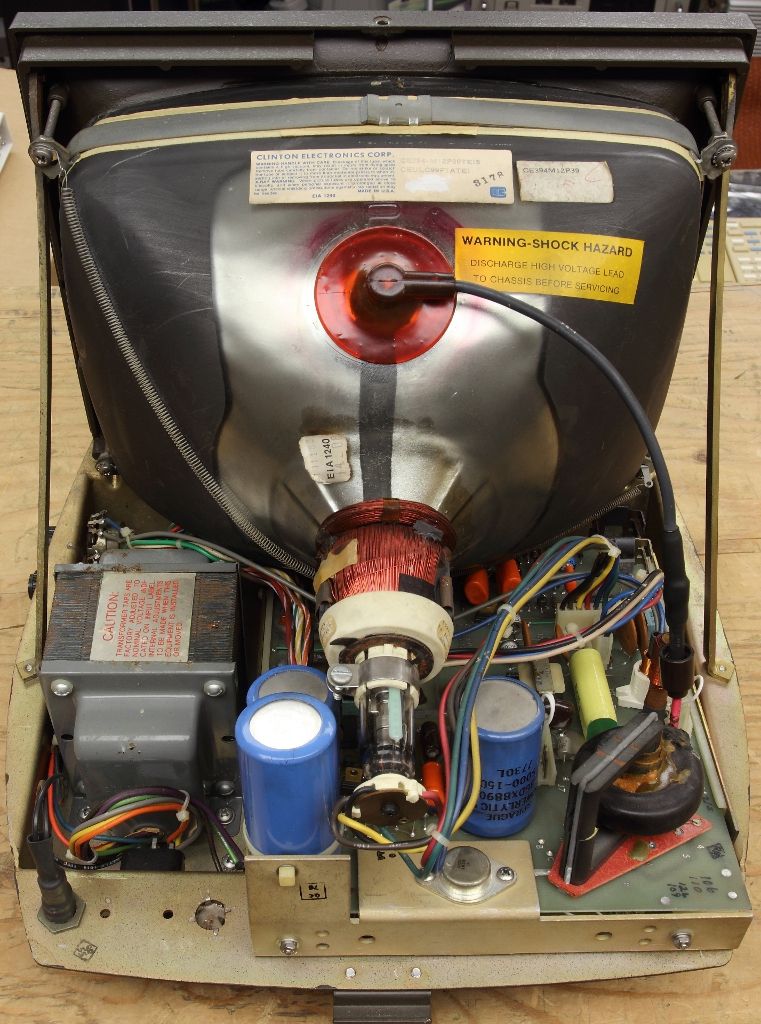
Excluding the nasty cataract I still need to remove it has a P39 green phosphor similar to the IBM 5151. This is the heaviest monochrome monitor you will ever pick up because the entire front bezel and base is made of metal while inside also contains a very large transformer. As you can see from the back the terminal connection is a 20 pin double sided edge connector that allows all signals to pass through and up to four terminals to coexist on a chain and share the same video signal. Each terminal has a mostly separate keyboard which almost does not interact with the display at all however if you opted for it, the logic for a light pen can be installed inside the keyboard on its own pin header and an extra port on the back of the keyboard is the pen input. The video signal is analog and quite close to composite, not not exactly I think. while the schematics we do have for the monitor does not state the signal is anything special, supplying video through pin 10 and a return ground it sees something but cannot sync to it. Rather than begin fiddling with all the adjustments right now I'll wait until we are ready to bring the system up.

7d985d02-984d-45a4-b63d-7de5d3063ab5.jpg

61ae8ff5-85bd-4e85-afb8-a9bc13616640.jpg


The analog board and the terminal board are removable on edge connectors. Both took a recap and the larger caps were separately tested and found to be good.
 
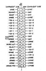
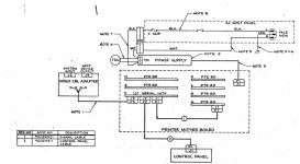
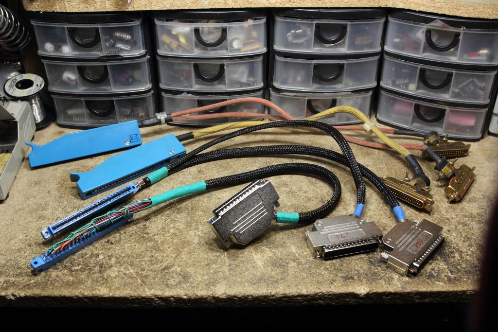
After months of procrastination and sourcing the correct parts I've also now made copies of the two cable harnesses that connect the I/O boards to the mezzanine distribution board. the originals can now be returned to MITA. I have also made pinout sheets for both cables since they were missing for the other documents uploaded to Bitsavers.

ca576002-2bd6-42cc-ae9a-aca9d811e4cd.jpg


One more cable needs to be made and that connects the I/O board to the power supply, then we are finally ready to put it all together and turn it on.
 
So here's one that got away. I can't tell the origins of the photos or the listing but it got picked up and advertised by the etsy-clone resellers. One place still had the listing up but I'd hesitate to try and buy it if everyone now 404's.

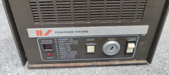
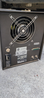
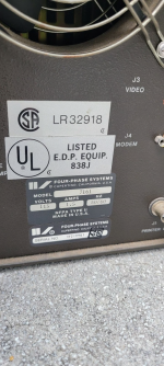
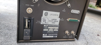
This is a "7161" Looking at the front you have a power switch, a keylock for booting the box and a 7-segment LED indicator for status codes or if the processor has halted. The back has ports for a standard terminal with a Winchester plug, two BNC jacks for printers (Cool, I wonder what type of interface THAT was) and what is probably a synchronous serial port for an external modem..

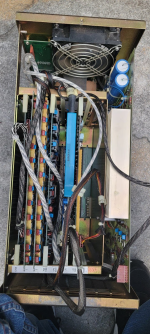
The real magic is inside where we can see it has a switchmode PSU, two RAM boards and variant of the CG, DT and processor boards. It's new enough that they were using socketed EPROMS, judging from the photo.
Slightly unrelated, in my recent venture into bubble memory I was talking to our local Four-Phase engineer and he mentioned they did briefly experiment with bubble memory for storing bootstrap settings but ended up abandoning it because of retention and reliability issues.
It feels like it's just a remote establishment controller but I *think* this was one of Four-Phase''s super low-end models that *is* just emulating an IBM establishment controller with support for two terminals, printers and one modem, internal or external.

It's alluded to in https://bitsavers.trailing-edge.com...hase/M11-435-10_7908_Four-Phase_System_IV.pdf

Systems IV/30 and IV/55 are intended for use in locations requiring only one or two data entry/data displaystations. Such stations are typically limited to the dataentry and report printing functions, leaving all data processing functions to the remotely located host computer.

The /55 specifically includes what I think is the 8250 diskette controller and drive.

Here's the photos for archival purposes.
 

Attachments

  • m56704818943_1.png
    m56704818943_1.png
    2 MB · Views: 9
  • m56704818943_2.png
    m56704818943_2.png
    1.9 MB · Views: 9
  • m56704818943_3.png
    m56704818943_3.png
    2 MB · Views: 9
  • m56704818943_4.png
    m56704818943_4.png
    1.9 MB · Views: 9
  • m56704818943_5.png
    m56704818943_5.png
    1.9 MB · Views: 9
  • m56704818943_6.png
    m56704818943_6.png
    2.4 MB · Views: 9
Last edited:
Last major progress report for at least the week.

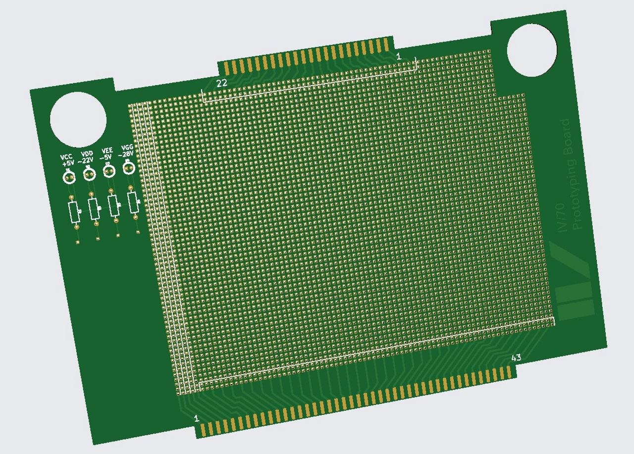
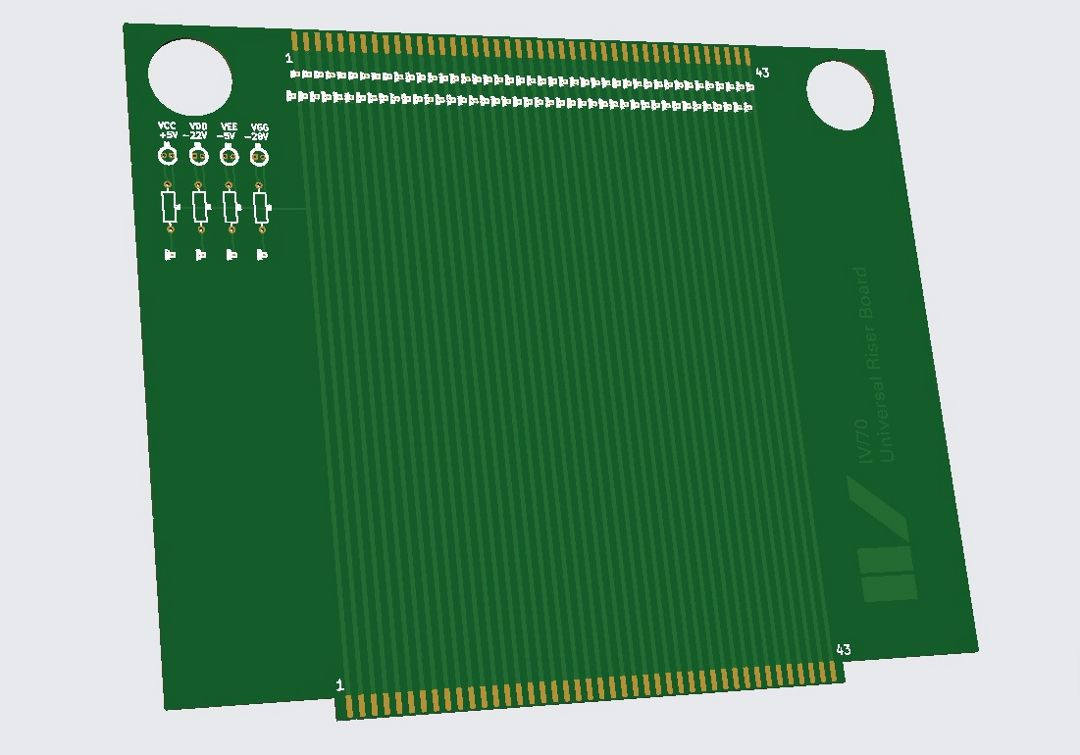
On a whim I decided to draft out an idea for what boards it might be practical to build for now and with the help of someone WAY more skilled with CAD than me we now have designs for prototyping boards and riser boards so we can probe boards while they are loaded in the machine. Probably the first new boards designed for a Four-Phase machine in 40 years.

1bf1122f-453e-48f2-8d23-5fdaed8da71a.jpg

f4da032d-c415-45af-b1fc-30532517ea61.jpg


Very simple boards with finger holes rather than plastic latches so they can be more easily pulled out with locations for LED's to indicate what each power rail is doing.
 
Back
Top