• Please review our updated Terms and Rules here

Four-Phase Systems IV/90

I was sent another set of photos of my machine when old_68K got it out of the pole barn and there's two good photos of the card cage.

Four_Phase_Systems_CPU.jpg

fps012.jpg


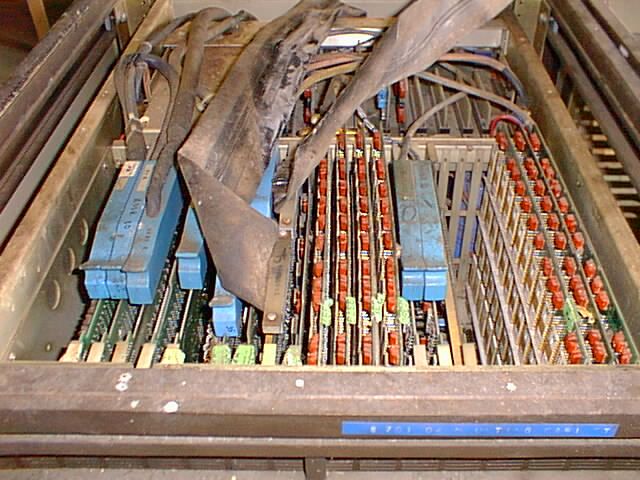
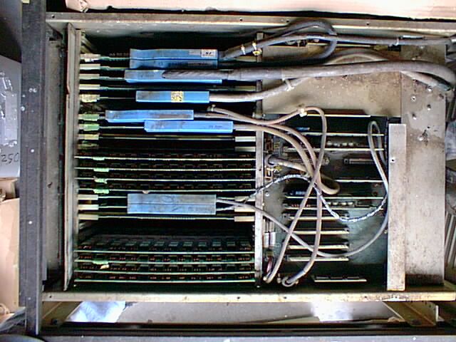
My current board manifest lists 20 cards and the photos show 23. There's a deeply recessed board in the MP slot that is missing, but the two I/O INT(erface) boards and its associated cabling to the terminal distribution board are also missing, So there are boards that at one point were pulled after this was rescued and for the last two weeks I've been trying to reach @old_68k (last seen here on the forums in January 2023) since between then and now he's the only person to of touched this machine and without those boards, well that's it folks. I can't continue.

On a more humorous note, I paid too much for this but I now have a second keyboard assembly and the keyboard housing for a terminal. It looks like it was some sort of retirement gag.

CGS_12452.JPG

CGS_12453.JPG

CGS_12454.JPG

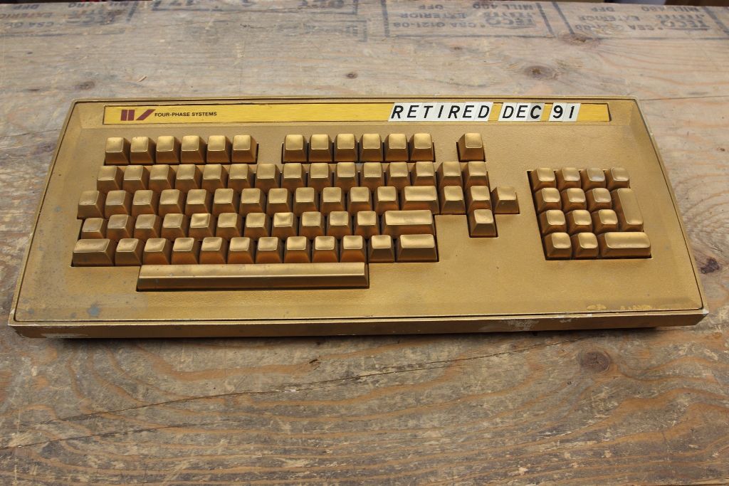
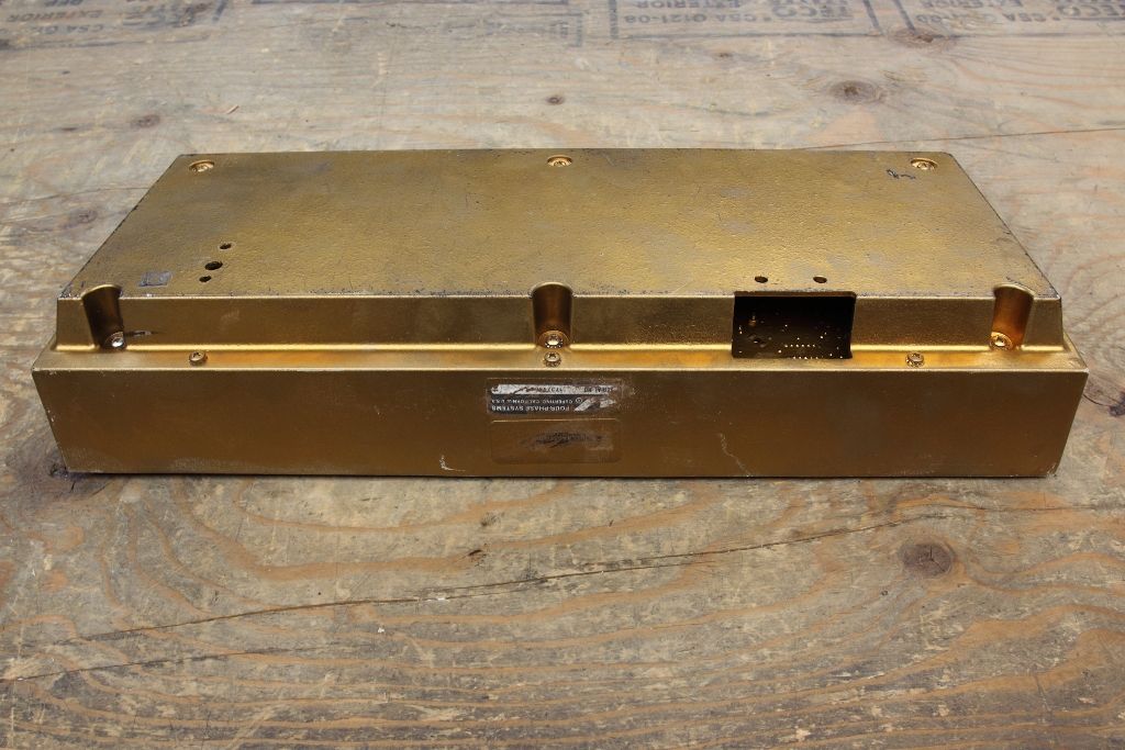
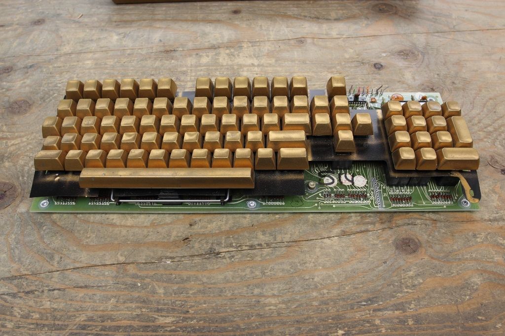
What I am going to do is because my spare inner keyboard assembly isn't in the best condition I'm just going to switch the keycaps over (and try to get the paint off these ones) but I'm going to leave the gold paint and the lettering.
 
Last edited:
Cap kit in and I redid the "bottom" board on the power supply. I forgot how heavy the thing was. Also retested the larger caps on the topside and they still test OK for ESR and capacitance after seeing about an hour's worth of runtime this year.

5V comes up and everything needs a slight adjustment but I've noticed it doesn't like warm starts. If you cycle the power and you don't wait a minute or two the +5 doesn't come up. Speaking on the expert about this (who noted he designed the PSU's regulation boards and had the rear test points added. Thank you. ;) ) he mentioned that the lower board wasn't his design but they had problems with the 1% high precision resistors (such as R9)

One thing before I go tweaking the voltage adjustments is (and you can see the board back on the first page) most of the pots make sense, except for "+5 I-LIM", which I can only guess is in-rush voltage limiting for the +5 rail and the +10v adjust I have no clue about. That's not available on the test point and I don't actually know WHERE +10v is available to check and adjust.
The other is loading. +5 makes sense because, so I'm hanging a 2A load from it but the remaining -5, -22, -28, +24 and the mysterious +10v I do not have any specifications on what their peak operating load limits are. Should I try to just put a 500ma load on them and adjust from that?
 
Nah the power supply is now giving me trouble. It's been totally fine for the last year and when I pulled it twice for cleaning and inspection and testing but now it wants the say it's not having a good day.
On the table I load it with 2A on the +5 and other than the above rail on occasion refusing to come up it looks solid and I can tweak all the other voltages.
Attach the harness and bring it up still on the load but now with the backplane and the front panel now that I've replaced the two filter capacitors in there and it's still doing good, but the power supply starts hissing like its becoming increasingly unhappy as I add additional load to it. It's not a switcher, so hissing isn't a good sound.
Add in the ram boards as a load and now with and without my load attached it still has good rails (plus or minus .5 volts which I can correct with the adjustments), but the hiss becomes a squeal. There is obviously something in the power supply that is now extremely unhappy and I am not proceeding further until I can figure out why it seems the +5 regulation boards are complaining so much.
The power supply for the IV/70 is one of the few schematics that MITA doesn't have and my other contact while this is solidly in his time at Four-Phase (he designed this section of the power supply and you have him to thank for the rest test points) it's been 50 years and he can't remember a lot else beyond the Dale precision resistors for the adjustments giving them grief. Removing the +5 regulators that sit on either side of the transformer are a pain because you have to unsolder and dewire the lower control board, then you can reach the screws to remove the boards as modules. If this is a weak diode or a failing component beyond another visual inspection I don't really have proper tools available to be testing this and I still have the spare CPU board on loan that I would like to return in a timely manner but with the PSU doing this I cannot risk installing it and testing.
At this point there's three people on this planet who know these machines, I'm one of them and we're all out of ideas.

Additionally I talked to old_68k and he confirmed the photos at the top of the page are not this machine. It's another system that was identical in spec and filth but that means this machine's missing the I/O interface and that I can tell the front panel might be able to talk to the CPU if to tell you that it's alive but the I/O expansion section and the entire terminal interface section is otherwise detached from the CPU, system memory and the terminal character generation and display memory. Unless by some miracle more of those boards and cables surface this machine will never run again which a year into this project was not what I wanted to find out.
 
Last edited:
God DAMMIT ebay. Four-Phase is a saved search and told me nothing. Not a single damn email or notification and I was at a company event last night when it ended.
Ran it manually just now and boom, there's TWO listings it didn't tell me about in Vernon. What the hell did it not understand about "if the description says "four-Phase", tell me regardless of location".

Edited: son of a $#%#$% it's in Vernon. It's the town right next to me.
Well I can try asking them if they have anything else, like the boards these were stripped from but looking more into the seller it's just another Thrift Shop Vulture and probably doesn't even remember what store they found it in.
 
Last edited:
Hello NeXT,

you did an excellent work at this Four-Phase System! By accident I got a front panel of this machine.

I have here a front panel including the keyswitches, but without the labeled plate. A lot of the lamps are missing or defect.
When you need some more information about keyswitches, just let me know.
IMG_1873r.JPG

Do you have a schematic about the front plate or do you know which voltages I've to use to test the panel? As far as I can see there are connectors E1 .. E5 on it which are used for power.

I found in my stuff two knobs with bayonet nut connectors - I don't know if they would fit into the rack but they could optically fit to your front panel. My uncle used them on an apparatus he made in the late 60s or beginning 70s.
Just let me know if you need them or if you need some measurements of the knobs.

IMG_1890.JPG

Best regards,
Josef
 
Oops, sorry. I was at VCF East and didn't see this buried in my reply notifications.
Yes I do. I was going to say it's on bitsavers but I guess the cabinet photos have not made it up yet so I'll pull it out tonight and see how to send it.
 
The picture is perfect. Thank you very much.
Yesterday I tried to put some action on the lamps with a Arduino Nano: Blinkenlights

Sadly the control panel is the only thing we have from the Four-Phase Systems computer.
Now we want to try to replace the three IO chips with a microcontroller each so that we can control all the lights and read all the switches.
 
I do not have photos of the missing I/O interface boards. The best thing that has been sourced was board schematics and layout diagrams (they are on Bitsavers), which add a bit more gloom because they are dominated by more Four-Phase ASIC's to which have no documentation.

Sadly the control panel is the only thing we have from the Four-Phase Systems computer.
Now we want to try to replace the three IO chips with a microcontroller each so that we can control all the lights and read all the switches.

I have high-resolution photos of the front panel's main board. They too got sent to Bitsavers.

Edited: ooh! hey, all the pictures went live on Saturday! Thanks Al!

The front panel is listed as /pdf/fourPhase/Pictures/11001131-C_BACKPLANE_and_CHASSIS/11001481-D-*.JPG
 
Last edited:
Thank you for the high-res pictures! They helped a lot.

We are currently reverse-engineering (a little bit) the control panel and I de-soldered all the sockets to have a better sight at the traces.
Do you happen to have a schematic for it (90063031 E)? We plan to replace the three IO chips with an adapter and a mikrocontroller each to use the panel at least for some blinkenlights :)
 
If it's not on Bitsavers, it's all I'm aware of that exists unfortunately. I've been on a bit of a crusade for the last year or so trying to gather up as much as I can find and get it published online so if you know anyone with...well anything really that pertains to Four-Phase there's a bunch of folks who would like to hear from you. :)
 
Back
Top