• Please review our updated Terms and Rules here

Honeywell 200 resurrection

God that really was the most Saul Bass looking computer ever made.
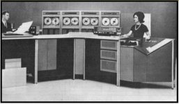
I read somewhere that Honeywell did employee design consultants on its development but I don't know who they were. A lot of thought seems to have gone into not just the internal technology but the ergonomics and visual appeal. It seems obvious that simple coloured symbols on the buttons would catch the eye of an operator more clearly than words once the meaning of the symbols was known.

Honeywell 200.jpg

Also I mention on my website the unusual but highly practical and economical design of the triangular model 223 card reader (on the right in the above picture) used with the H200. Having seen one in regular use it seems obvious that a triangular design allowed space for a long input hopper tilted towards the operator, which made loading it easy and also aligned the corners of the cards rather than just one edge as would have happened if the hopper hadn't been tilted over. It seemed mad to include an almost triangular cabinet in a system that otherwise used conventional rectangular ones but that was actually the best design for the task. As with the use of low level cabinets rather than tall ones the objective was to give the people the space to work efficiently rather than simply cramming the machinery into the smallest possible space.

The emphasis on good and original design extended into the clear layouts of the training material and also the marketing material. The imaginative series of model animals constructed entirely out of electronic components made the H200 marketing campaign highly memorable and the original models are now very desirable works of art in their own right. I myself just have a small collection of pages from magazines from that era containing a number of the advertisements featuring these models including the first, a bird escaping from a cage with the heading "You're free!" to promote the Liberator program that enabled the machine to run IBM 1401 program code.

The daughter of Dr. William L. Gordon, the chief designer of the H200, told me that he was very proud of that machine and he often used the word "elegant" when talking about it to his family. That elegance appears to have been a central theme in all aspects of its development and marketing, which is what now makes it memorable rather than any aspects of its technology. On this site people may mention the ground-breaking technological aspects of other computers but about the H200 they are more likely to recall its pretty flashing lights, its colourful painted buttons more suited to a baby's toy and a weird triangular card reader which held the cards at a crazy jaunty angle ... and yet it was a brilliant machine to work with as well.
 
Last edited:
The IBM 1402 reader/punch, among other bits of IBM unit-record equipment could be had with the slanted input tray. See here for example.

I liked the vibratory table feed on the CDC 405 reader with vacuum feed. CDC used this design for a long time. https://commons.wikimedia.org/wiki/File:CDC405Top.jpg

That slanted input tray only sloped in one direction but the 223 input tray tilted sideways as well as sloping so that the cards also slid sideways to align properly. In fact there wasn't really an input tray as such as it was simply the top casing of the reader with just one side panel to retain the cards and further up that same sloping casing held the row of buttons that controlled the reader, so the design was incredibly simple. This frame below from the film Billion Dollar Brain illustrates this with the buttons just visible in the top left but that entire film sequence of a 223 reader being loaded can be found HERE. The relevant part starts forty seconds into that clip. It can be seen clearly that the cards were placed in the feeder leaning over to one side to align the corners.

223 Card Reader.jpg
 
I'm attempting to contrive a pulsed DC PSU suitable for my control panel SCR controlled lights by removing the smoothing capacitors from a PSU from a 1970s Honeywell Keytape machine, which was based on an H200 magnetic tape drive so is compatible with my other H200 technology. This PSU uses a constant voltage transformer but when I powered it up for the first time in fifty years the transformer emitted a very unhealthy sounding low frequency growl. I checked the waveform of the unsmoothed rectified output from the nominal 15 volt circuit with my oscilloscope with the result below. It was understandably difficult to get the scope to lock onto the signal.

CVT on.JPG

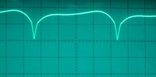
I checked the CVT circuit capacitor with a component tester and it was identified as being 4MFD but that didn't imply that it is still capable of handling the voltages encountered in the CVT circuit, so I tried leaving it disconnected to disable the CVT circuit altogether so that the transformer was free running. This resulted in a more acceptable buzz and the waveform below.

CVT off.jpg

Is it just me or does that look like something from Close Encounters of the Third Kind? No, the buzz is just at mains frequency with no other musical notes involved. It looks as though the transformer core may be saturating but that doesn't entirely explain the waveform's resemblance to something in Monument Valley. There is the added complication that although the transformer and CVT circuit are designed for 50Hz operation to suit UK supplies it nevertheless needs a USA AC supply voltage, so I am having to run it from a separate UK to USA step-down transformer as was done inside the original UK Keytape machine. Nowadays widespread local use of electronic devices plays havoc with the allegedly sinusoidal waveform of the mains supply entering the property, so such distortions are unavoidable but they do make estimating the equivalent RMS voltage of the output that much more difficult. It looks like I am going to have to apply some of my school calculus to that problem as I don't have an old-fashioned hot wire voltmeter to assess the voltage directly. The scale on the scope graticule is volts with gridlines at five volt spacings, so the RMS value may fall a bit short of 15 volts, but that will give the filaments in the control panel bulbs a longer life.
 
Is your UK to USA step down really a simple transformer? Or is it a modern device that probably uses a switching power supply? I ask because I used a 12VDC-to-120VAC 60Hz power inverter to fake a telephone ring signal (modified it to drop down to 20Hz). The output waveform of those devices is not at all sinusoidal and would probably not do pretty things if fed into a transformer (including make strange noises). The waveform I observed was more like a step pyramid (with only a couple steps). The device also could fall out of "normal operation" and change the waveform when different kinds of loads were applied.
 
It's definitely a transformer, which is evident from its weight alone, it being rated at 250 Watts. Also it doesn't even have a case except for a distinctly transformer shaped housing and a small one over the side that contains the wiring and USA style domestic three pin sockets. Speaking of which, it is extremely difficult to get ordinary domestic USA style three pin plugs here in the UK. That's probably a little detail that you people over the pond wouldn't even think about but the most trivial items such as these plugs and the UNC screws and nuts used on Honeywell equipment are alien objects over here and one has to find specialist suppliers for them.

Returning to that transformer, it was originally used in the office where I worked to power a Flexowriter during the 1950s and 1960s, so dates from well before switched mode PSUs became commonplace. Therefore it is even older than the Honeywell PSUs that it is now powering but as it is just a simple well made transformer it is still as good as new.
 
OK, so the output of that transformer should be a sine wave 50Hz signal. That makes the odd waveforms more curious. Sounds like some "bad" components someplace? Could be diodes, too.
 
OK, so the output of that transformer should be a sine wave 50Hz signal. That makes the odd waveforms more curious. Sounds like some "bad" components someplace? Could be diodes, too.

With the CVT capacitor disconnected the only components in circuit are the UK-USA stepdown transformer, the 15 volt constant voltage transformer and the diodes, but as there is no load on the circuit there is very little current through the diodes. Also the signal on the AC side of the diodes, i.e. at the output from the transformer winding, looks similar to that on the DC side except for the inversion of the negative half cycles. Therefore the diodes don't appear to be an influence unless they have significant capacitance. However, a relevant point about the waveform is that the rising and falling sides are exactly the same shape, so that suggests to me that there isn't a capacitive influence involved. The distinct change in the slope of the waveform occurs at about 11 volts, the peak voltage being almost 19 volts, so something definitely appears to change at that point.

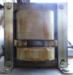
One possibility is that the effect arises from the magnetic circuit rather than the electric one. A CVT has two magnetic circuits interacting with each other. See the picture of the transformer below. The lower winding is the currently disconnected constant voltage control winding and the normal magnetic circuit is divided into two by the extra iron stampings wedged between the two windings. These inserts inevitably leave air gaps at their ends and these plus the way that these stampings are apparently simply taped together may be the source of the buzzing noise. One possibility is that at low levels of magnetisation the flux all circulates around the main core but at higher levels it also jumps the air gaps and takes the shorter route through the inserts. This could result in two distinctly different rates of change of the voltages in the windings as seen in the waveform. I'm not that well versed in the electromagnetics of transformers though, so this idea may just be nonsense, but there is certainly an additional factor there to be considered.

CVT.JPG

I'll find out more about the practical aspect when I connect the PSU to the control panel to work under load. I have now bought the correct military style nineteen way MIL-5015 connector needed to feed the supply into the control panel through the proper external connection.

Today being Sunday I won't be working on the project any more just now.
 
Last edited:
Ah, I had missed the CVT aspect. Although, I wonder how that extra winding, being disconnected, could be interfering at all. That got me thinking, though, about the fact that you have two transformers working in (possibly) close proximity. How nearby is the 220-110 transformer to the 110-15 one? Maybe tip one 90 degrees so that the magnetic fields won't align?
 
And, as I mentioned in another thread, the waveform coming out of the output of a constant voltage transformer is not pretty. See:https://www.eeeguide.com/constant-voltage-transformer-cvt/ for example. Essentially, a square wave superimposed on a sine wave, or vice-versa.
Note also, that the value of the tank capacitor has to be adjusted if you're going from 60Hz to 50Hz applications. They don't call it "ferroresonant" for no reason.
 
Thanks for all the comments guys.

Ah, I had missed the CVT aspect. Although, I wonder how that extra winding, being disconnected, could be interfering at all. That got me thinking, though, about the fact that you have two transformers working in (possibly) close proximity. How nearby is the 220-110 transformer to the 110-15 one? Maybe tip one 90 degrees so that the magnetic fields won't align?
I should mention that I got the windings mixed up in my previous post. The bottom winding is the mains primary and the constant voltage winding is overlaid onto the low voltage output windings. I have just checked the bundle of wires coming from the windings.

I am aware of the need not to align potentially saturable inductors like CVTs if they are close together but in this case the two transformers were about three feet apart. Apparently CVTs are notorious for leaking magnetic fields everywhere and another model of Honeywell computer used at my company, the DPS6, had the PSUs with CVTs that powered the eight inch floppy disk drives enclosed in thick steel cases to avoid magnetic interference with the big floppy disks nearby.

Without the capacitor connected to the Ferroresonant coil you will get very little out of the low voltage windings on the transformer.

As I mentioned I haven't tried using the CVT under load yet but have only tested the off load voltage. It was also primarily an initial test of the old components involved which, as I mentioned, hadn't experienced any current through them for over fifty years previously. The fact that, with the capacitor connected, the transformer growled angrily, sounding as though laminations were shaking loose, caused me to try disconnecting it.

Regarding checking out these old components, I removed the smoothing capacitors from the original DC circuits in the PSU not just because I need unsmoothed rectified AC but also because I haven't reformed them yet after many decades in storage and I need to revive them very carefully before considering using them. I have already done this successfully with a similar PSU of the same age and have been pleasantly surprised that these big ancient electrolytics have so far functioned consistently while supplying the power for testing my computer's logic modules and main memory unit. There are six such capacitors in the PSU with values of 160,000 MFD and 90,000 MFD, so they need some respect.

I can recall as a boy reading that the Farad was a completely impractical unit because Farad capacitors were virtually unheard of then but I noticed that a current catalogue of capacitors now lists a 160,000MFD one as 0.16F and the list then goes on into the multi-Farad range, so times have distinctly changed. If we can eventually get electric cars to run on capacitors rather than batteries that will make refuelling them much faster. Just a kite and a good thunderstorm should be enough as a last resort if you are caught out in the middle of nowhere without power.

And, as I mentioned in another thread, the waveform coming out of the output of a constant voltage transformer is not pretty. See:https://www.eeeguide.com/constant-voltage-transformer-cvt/ for example. Essentially, a square wave superimposed on a sine wave, or vice-versa.
Note also, that the value of the tank capacitor has to be adjusted if you're going from 60Hz to 50Hz applications. They don't call it "ferroresonant" for no reason.

That's odd about the waveform because I have read that a CVT will actually output an even better sinusoidal wave than the one input because of the resonant circuit involved. The equipment that the PSUs were removed from had already been adapted by Honeywell for use in the UK, so hopefully they dealt with the tuning of the resonant circuits for 50Hz operation.

In order to get the SCRs and lights in the control panel switching properly I need a pulsed DC power supply at a nominal 15 volts RMS and about 7 Amps maximum but the waveform probably doesn't matter too much so long as it drops to zero regularly to turn off the SCRs. While any such waveform would do, the one shown in my previous post contained worrying sharp spikes to zero, which suggest to me that the tank capacitor may be faulty or laminations are working loose. At worse there could be an intermittent break in the wiring of the transformer windings as wire that old can become very brittle. This PSU was very similar to the other one that I use to provide DC supplies for the computer except that it had an extra 7 volt output so that there were two such both rated at 15 Amps maximum with a standard design current load of 11 Amps each. When I saw this modification I did wonder whether the transformer actually had the reserve capacity to supply an additional 77 Watts, so maybe it has already had an unreasonably hard life and is entitled to be noisily grumbling about it now. Just how much can a CVT be overloaded before it gives up trying to keep the output constant or is it actually prepared to die trying?
 
That's odd about the waveform because I have read that a CVT will actually output an even better sinusoidal wave than the one input because of the resonant circuit involved. The equipment that the PSUs were removed from had already been adapted by Honeywell for use in the UK, so hopefully they dealt with the tuning of the resonant circuits for 50Hz operation
Nope, a CVT outputs a trapezoidal waveform, basically a summation of the energy stored in the tank circuit with the secondary sinusoidal output. See, for example, https://www.nutsvolts.com/questions-and-answers/ferroresonance-transformer. Basically, a clipped-top sinusoid. CVTs are great for taking up the slack when the line supply drops--they can usually handle a 40% drop in line voltage. But there's a price to pay. If overloaded, the output voltage drops like a rock. They're much less efficient than regular transformers and oddly, as load current drops, so does efficiency. Because of input surge requirements, they tend to be oversized for the constant load requirements, thus operating in their least efficient mode. As a result, they tend to run hot.
 
Yes, they aren't by any means my choice but Honeywell seem to have been keen on using them back in the 60's and 70's. In fact they used many inefficient techniques such as shunt voltage regulators which simply sank sufficient excess current to drag the voltage down to the required level, the matching PSU containing a series resistor to permit this to happen. In fact I take advantage of this in my temporary bench power supplies for the computer by monitoring the excess current being drawn by each of the shunt regulators. During construction I am mainly interested in how much current is available to run more logic boards rather than what the total load currently is. When I have finished construction I will consider building PSUs to suit the total current requirements.

To avoid voltage loss in connecting cables between the shunt regulators and logic boards the 5 volt regulators are contained on standard logic boards so that they can be plugged into the backplane right next to the logic. They are intended always to sink an appropriate proportion of the total current required by the whole backplane to accommodate variations in the demand. On backplanes with thirsty logic boards up to four regulators each capable of sinking 5 Amps of excess current were installed to provide the appropriate margin. I suppose at least it made the thermal state of a backplane more consistent as the whole thing would always consume the same total wattage regardless of how much power the logic was actually using. No doubt for authenticity I will keep to this design. However, if the current drawn from the PSU is kept constant in this way then a CVT would only be beneficial if the mains supply were prone to significant variation and I don't think our local domestic supplies here are.

The lights in the control panel will demand vastly varying current from almost nothing up to 7 Amps, so the shunt regulator approach used with a conventional transformer might be appropriate if it were possible to apply it to an unsmoothed waveform. Offhand I'm unsure how that could be achieved. It's an interesting problem. Perhaps top clipping of the waveform would be adequate to maintain the brilliance of the lights at an even level. Of course the simplest shunt regulator is just an additional extra big light bulb that's on all the time. That would at least reduce the percentage variation in the total current demand.
 
The rectified waveform from my CVT looks much better under a 40 watt dummy load and the buzzing is quieter. As the current demand from the lights in the control panel varies so widely I may have to find something else to put a more constant load on the CVT apart from the panel. However, as the lights do all draw a constant priming current to keep them almost glowing even when "off" that may be sufficient. I still have some work to do to bring the panel and CVT PSU together though.

CVT under load.JPG
 
One thing's for sure with Honeywell...the wires they used as well as the zip ties were made to last! I've been rewiring a control panel for the last 2 weeks and the wires are like "memory wire" and want to retain their shape. The zip ties are like new. I have some newer ones (probably from Harbor Freight) that went brittle in less than 10 years.
 
I have now tried connecting the control panel to the CVT-plus-diodes based PSU and during this trial panel lights did both come on and go off, so the intermittent supply waveform shown on my previous post is shutting off the SCRs as expected. A supply similar to this must have been used in the original H200's as my control panel is completely unmodified and simply connected to the PSU through its original power connector. The built in filament test provided by the INITIALIZE button proves this to be so, so the signals from the CPU must also only have been responsible for turning lights on. Therefore the PSU probably turned all the lights off every 10ms (at UK 50Hz mains frequency that is, assuming that the original PSU wasn't designed to pulse faster than the mains frequency, which would have been an unnecessary expense) and how bright a light appeared depended only on when within each 10ms period the related input signal first turned that light on regardless of how fast the signal was actually changing at the CPU end. This is of course much like the way that SCR based dimmer switches work with incandescent house lights.

One thing's for sure with Honeywell...the wires they used as well as the zip ties were made to last! I've been rewiring a control panel for the last 2 weeks and the wires are like "memory wire" and want to retain their shape. The zip ties are like new. I have some newer ones (probably from Harbor Freight) that went brittle in less than 10 years.
Wires retaining their shape may be the result of insulation hardening with age but it may be possible that the copper itself experiences long term age hardening as well as the well known work hardening. In my control panel I found a few wires that had snapped, the copper itself fracturing cleanly across leaving a crystalline pattern on the broken ends. We are used to thinking of copper as being very ductile but that isn't always true.

In the past there were fewer types of plastic available for making zip ties whereas nowadays there are many formulations and some are more suitable than others. I have had some bundles of ties that have become brittle even before I have got around to using them. Even at room temperature some ties can become brittle and fracture.

Regarding memory effects in wires, I find it really annoying that plastic leads provided with new equipment are invariably permanently kinked up as a result of having been folded up tightly to be packed into a small space within the packaging. It is pointless supplying a so-called one or two metre lead when it so persistently concertinas up that it can never be made to span the stated distance. This built-in kinking also results in tangles that frequently need to be unravelled. Every time my wife gets her hair drier out to use she complains about the length of time it takes to unravel the mains lead. Eventually I will replace that lead with non-kinking rubber insulated cable. Some cables eventually end up resembling strands of DNA through differential shrinkage of the layers of insulation.
 
Last edited:
I did a rough calculation of the RMS value of the voltage supplied by my pulsating waveform and it came out as 14.6 volts RMS, so it's right on target. Also it varies very little regardless of the load, which is good.
 
Did you measure the voltage while holding down the INITIALIZE button, worst case? I calculated that just lighting the ones on my panel will draw at least 6.4A. It has 4 lamps that are larger than the 382 bulbs and probably draw a little more current. Interestingly, I found a both a 387 (28V) and a 382 in each of the AC ad DC off buttons. I'm afraid to pull the reset bulbs for fear of messing up the littler red booties on them.

I think you are right about the insulation being the source of the memory wire effect. I didn't have any connections where the copper fractured but I have seen that somewhere before.

I find it a bit ironic that the INITIALIZE button doesn't have any bulbs and isn't even wired for them. :D
 
Back
Top