Desperado
Veteran Member
- Joined
- Nov 25, 2017
- Messages
- 7,880
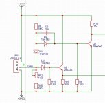
Thanks so much Doc Antony!@Hugo Holden , @daver2 , that's a prewiev of pcb workinprogress
Great job!
| VCF West | Aug 01 - 02 2025, | CHM, Mountain View, CA |
| VCF Midwest | Sep 13 - 14 2025, | Schaumburg, IL |
| VCF Montreal | Jan 24 - 25, 2026, | RMC Saint Jean, Montreal, Canada |
| VCF SoCal | Feb 14 - 15, 2026, | Hotel Fera, Orange CA |
| VCF Southwest | May 29 - 31, 2026, | Westin Dallas Fort Worth Airport |
| VCF Southeast | June, 2026 | Atlanta, GA |
Thanks so much Doc Antony!@Hugo Holden , @daver2 , that's a prewiev of pcb workinprogress
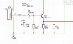
1 Kohm !@Desperado - do you still have the potentiometer connected in place of C1 and what value is it?
Dave
In this oddball case that might not be a good idea, because regardless of the amplitude of the signal at the diode's D1 and D3, the circuit relies to an extent on the input voltage falling close to ground as the reference point where the syncs are.I would normally wire JP1/3 to one end of the potentiometer. Ground to the other end of the potentiometer. And the wiper of the potentiometer to (in this case) D1 and D3. I would further wire the potentiometer so that turning the potentiometer clockwise increases the signal (moves the wiper closer to the JP1/3 signal source).
This prevents the source signal being accidentally shorted out, and would (in general) provide less of a load change to the signal source as the potentiometer was adjusted).
Dave
Thanks Doc!Add 100 ohm resistor
thanks for the title, but I'm not a doctor, I'm a simple electronics technician who can carry out the instructions of an engineer but not competent in designThanks Doc!
You are too modest! You worked at Commodore in the 90s!!thanks for the title, but I'm not a doctor, I'm a simple electronics technician who can carry out the instructions of an engineer but not competent in design
why???There will invariably be other modifications that we have to make...