@Hugo that is where I was headed... but I am now tempted to believe B1 p8 is clocking x4 due to A1 being broken... I guess we find out tomorrow...
That makes sense. The output signal from B1 is called the /RELOAD signal on other PET schematics and it determines the time everything in the vertical system recycles.
A1 is set up as a divide by 8 (overflowing) ripple counter with one of the 8 states 111 decoded by B1 pin 9, 12 & 10.
It would pay to check the clock frequency fed to A1 on its pin 1. If that is normal then:
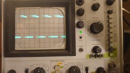
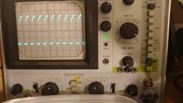
Since the pulses out of B1 have not disappeared, but are clocking x 4 faster, the first flip flop used in the '93 counter A1 ( input pin 1 output pin 9) must be working. Lets postulate two scenarios to work out which of the two IC's is defective:
1) If the outputs of the next two flip flops in A1 are stuck high, pin 8 and pin 11 of A1 stuck high, then the three bits would decoded by a working B1 and become a divide by two, instead of a divide by 8, making B1's output pulse on pin 8 4 x faster. .......alternatively.....
2) If we state that A1 is normal, then to get this effect, if it were an IC failure as the cause, it would be required that two of the input pins 12 & 9 had gone open circuit inside the IC B1 and assumed a high logic state and effectively B1 was ignoring these inputs. Seems a little less plausible, but it is still possible. I had a 74 IC once where two of its pins did go O/C and assume a high state internally.
In light of the above it certainly seems that A1 has likely failed and all we need to do is suggest scoping pin 8 & 11 of A1, no pulses & stuck high then A1 has failed. Normal looking pulses on 8 & 11 of A1 then B1 likely failed......but there is a big trap to fall into:
We could make a third postulate and say that both of these IC's are perfectly good, then what ?
The effect could also be caused if the tracks leading from A1 pin 8 to B1 pin 12 and the track from A1 pin 11 to B1 pin 9, were for some reason, open circuit.
")