Nivag Swerdna
Veteran Member
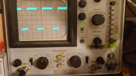
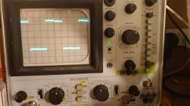
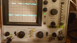
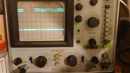
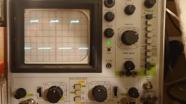
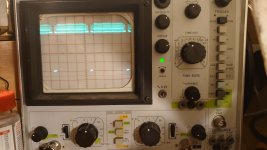
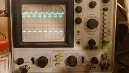
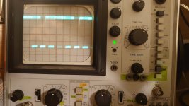
No worries. Scope pins 9, 8 and 11 of A1 and try and get nice traces. You could do pin 1 again too to keep @Hugo Holden happyOk so swapped out A1 and sadly no change on screen.
and order a 74LS20 for B1... (incidentally B1 is replaced on my PETunia; A1 is original; maybe I should have guessed the other way around but the A1 outputs looked wrong to me i.e. not like mine in #315)
Last edited: