• Please review our updated Terms and Rules here

Dead 2001

Just a thought, if you remove the data buffers between the 2114 RAM and the buffers to the CPU, do you still see the same 'rubbish' data line levels on the RAM pins?

If you do, it is pretty odds-on you have some RAM problems. A NOP generator may be the tool for this though.

Dave
Hey, no. This was one of the reasons I pulled the buffers, to see what the RAM does, if isolated from the data bus. It showed high and/or low levels on the various data lines on the RAM side, but these were all stable. Some were high and some were low, which I assume would be expected?
I can definitely plug the NOP gen in and have a look. I'm still learning how the R/W line should behave during various tests and this is a good time to see the effect of the test on the RAM.

For my understanding; The NOP Generator isolates the CPU from the data bus, right? In what state should the data bus be on the board, itself? Will it go to a specific state or can each data line float to wherever it wants to go? What would it look like on the scope?

Follow-up question, would it make sense to pull the data bus either high or low during the NOPs running and observe how that translate through the buffers?

PS. As you might have picked up, I'm using this repair as much to learn about the machine as getting it working. :)
 
That's great, I'm out of a job...

Can I retire now?

Dave
Only when it can fix PETs for us! :) Actually, thinking about it, I wonder how much of the info on this forum it has ingested.......

ChatGPT will have a massive impact on knowledge jobs where knowledge is just lifted and shifted, i.e. no new value is added to the knowledge. If you're a lawyer, GP or management consultant, for example, you should be worried. (Most) coders are also on top of the list with the cost to code projected to crash over the next few years.
 
>>> if isolated from the data bus. It showed high and/or low levels on the various data lines on the RAM side, but these were all stable.

I missed that. So, if the buffers are not in place, the RAM outputs look OK? By "OK" I mean that they fully swing from 0V to 5V with no 'daft' intermediate values. Is that correct?

>>> The NOP Generator isolates the CPU from the data bus, right?

Correct. The CPU data bus is isolated and forced to a NOP = $EA instruction. As a result, the CPU starts fetching (what it thinks) is instructions from address $EAEA (note that the restart vector is also forced to $EAEA as it reads the 2-byte PC from address $FFFC in ROM). The instructions the CPU thinks it is reading is always forced to $EA - so the PC increments and the next instruction 'read' and executed. As a result, all of memory (from $EAEA to $FFFF and then from $0000 to $EAE9 and then just repeat forever) is read.

If you have a non-CRTC PET, then you should see random rubbish on the screen. If you have a CRTC PET, then the CRTC is never initialised, and you will always get a picture of a black cat in a coal cellar at midnight (i.e. black).

>>> In what state should the data bus be on the board, itself?

It should correspond to what is being 'read' from the RAM/ROM or I/O space. If you have a logic analyser, you should be able to observe the ROM code being returned. However, the RAM contents will be uninitialised. However, with an oscilloscope, the data bus should be 'well defined' TTL logic levels with no 'bus contention' (e.g. 1.5 to 2.5 Volts or nasty looking waveforms). So the answer is, the data bus should be driven to defined states - unless the PET is accessing memory (or I/O devices) that do not exist - in which case the data bus should be floating - but it now depends upon which 'data bus' we are talking about and how some of the PET links may be configured...

>>> I'm still learning how the R/W line should behave during various tests

With a NOP generator, the R/notW line should be HIGH all the time. No writing should be taking place - only reading...

When using my PETTESTER there should be groups of WRITES followed by groups of READS - but the WRITES will be interspaced with reads as the CPU instructions are fetched from ROM. Not as easy to decode.

>>> PS. As you might have picked up, I'm using this repair as much to learn about the machine as getting it working.

And that is 100% the correct way to proceed. We would prefer you to learn (and do your own homework and ask questions) rather than it just being us doing a remote repair. You are doing pretty well though. Please keep asking away!

Dave
 
Thanks Dave,

With the NOP Gen in place and H8 and H9 removed, some lines do show activity (in line with the R/W pin-10). D3,4,5,7 stays low all the time. D0,2,6 are high but pulse low and D1 is low but pulses high.

R/W on the RAM shows a burst of 1MHz, every 130ms or so. During this time, the 4 data lines on the RAM that does not stay low, changes state.

This signal is a function of SELE (from G2) being combines with R/W and Ph02 via G4 and U9. From what I can see, these signals are all as expected. (Still trying to understand why SELE is used to enable R/W on the RAM.)

Anyways, I observed 4 permanently low, 3 high, pulsing low during R/W activity and 1 low, pulsing high, on the RAM data lines.
 
Only when it can fix PETs for us! :) Actually, thinking about it, I wonder how much of the info on this forum it has ingested.......

ChatGPT will have a massive impact on knowledge jobs where knowledge is just lifted and shifted, i.e. no new value is added to the knowledge. If you're a lawyer, GP or management consultant, for example, you should be worried. (Most) coders are also on top of the list with the cost to code projected to crash over the next few years.

Oddly there are so many parallels here. One of my patients who is a Jet Pilot told me that management wants to get rid of Pilots. They are a nuisance, have high salaries and various employment demands.

If you could run an Airline from a manager's desk, that would suit them better. He said, their second move will be to get rid of the co-Pilot (the first move was to get rid of the Navigator) Then they will replace the Co-Pilot with a Dog. The job of the Dog is to bite the pilot after he touches any of the controls.

The third move is to get rid of the Pilot.

Then, you simply have a large red cabinet in the cockpit with a glass front and a small hammer in a box. Inside that you install the "Duty backup Pilot" whose salary is now 1/4 of what it once was. It says on the cabinet, in white writing: "In an emergency, break glass and get Pilot"

It has long been a dream for management to dispense with annoying Pilots, Technicians and Engineers & Software Programmers too. With AI on the rise, and doing a stellar job at it, their (the management's) time has finally come to pass.

The only saving grace I can see here, is that who will ask the AI the right question ? Very much like the scene in iRobot: "My responses are limited, you have to ask the right question" Management might not know what that is.

So in the future the job of Technicians might not be to figure things out at all, or create anything original and new, but instead learn how to ask the AI the right questions. If this was the case in Einstein's time, I highly doubt if he could have come up with the Theory of Relativity. But we don't know this for sure, if a future AI Could have done it too.
 
Last edited:
So, with H8 and H9 removed, and the BBDn data bus only connected to the RAMs, it should be possible to 'force' the data RAMs to a value.

If you put some 10k pull-up resistors on the BBDn lines, then (on a write cycle) the data RAMs should write $FF into the RAM cell that is addressed. When the same RAM cell is subsequently read, it should return $FF.

If you run my PETTESTER, then we know that Pages 0 and 1 are written first, followed by read. On the read cycle, anything that reads that is not HIGH has either a faulty RAM data bit, or another RAM chip is pulling the data line low.

Likewise, you can swap the resistors over to pull-down, and you should only observe low signals.

This will tell us that we have a problem, not where the problem is (yet).

Dave
 
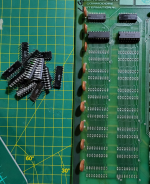
Decided to remove the next two 2114s and test them. Both failed in the RAM tester (new 2114s pass fine in the same tester).

Carried on, removing them one by one and test.

Every.Single.One failed in the RAM tester.

With only the bottom 1KB installed, PETTESTER in now happy and passed the first set of tests. Clearly failed the mem test at add 400.

Will now clean the board, socket and populate new 2114s. Hopefully we'll see 8KB of working RAM.

1683466131723.png
 
Star pupil!

Next would be the ROMs then. See if we can get PETTESTER to checksum as many ROMs as we can get...

Dave
 
Indeed, the ROMs next. But first the blank screen on BASIC 2 issue.

With the RAM working, I checked and still got the symptom that the machine boots BASIC 4 but not BASIC 2. In both cases, the 60Hz interrupt is being generated, so nothing stuck there.

Swapped out the VIA for a known working one and now she boots BASIC 2. :)

2001 BASIC 2.jpg

I tested this quite a bit while working on the other issues and it was consistent, boots in 4, never in 2.

Hopefully you clever people can figure out what's different between the two sets of firmware.
 
>>> Hopefully you clever people can figure out what's different between the two sets of firmware.

Actually it could still be the HDRIVE signal. The PIA (at G8) generates the interrupt. But the HDRIVE signal is also routed to the VIA.

The issue with the PET 2001 (and therefore with the 'old' BASICs) was the dreaded 'snow'. The firmware had to wait for the HDRIVE signal to update the screen.

With the later machines, the 'snow' disappeared because the video sub-system accessed the video RAM on the opposite phase of the clock (that the CPU was using). This was due to faster video RAM devices.

It is, therefore, just possible that the BASIC 2 ROM was polling for a signal from the VIA that never came - whereas the BASIC 4 ROM just didn't bother - as no one would be stupid enough to put BASIC 4 into a 2001 machine - they would just buy a more modern machine - wouldn't they!

They didn't think about PETs being museum artefacts in the future...

That is a thought at any rate...

Dave
 
OK, onto the ROMs. This is the current situation:

The board came with 4K ROMs for BASIC 2 and Kernal, in H1 to H4.

When I pulled the ROMs out the white sockets a number of pins broke off, specifically on the Kernal and Edit ROM. Some of the pins stayed in the sockets. The BASIC ROMs came out OK.

When I plugged a PETTESTER into the EDIT ROM socket (H3), it ran fine, so it looks like that socket is OK. Not sure yet about the other sockets, especially the Kernal socket (H4)

Couple of thoughts:
- If I want to use on-board ROMs, I need to stick with BASIC 2 as there is no B000 socket, needed for BASIC 4?

- Try and save the ROMs by soldering new pins on the original Kernal and Edit. not sure if the other pins are sturdy. Will have to test.
- If the Kernal and/or BASIC sockets are suspect, can potentially use the 'alternate' sockets as these are 4KB ROMs so should work in either socket for that function, right? H5, 6 and 7 instead of H1, 2 and 4. My understanding is that this will work.

I do have some TMS2532A and HN462532G EPROMs. These can work to replace the Kernal (and BASIC) correct? Are they pin-drop ins for the 2332?

/ADDED: Forgot to mention, I don't have a 25V programmer. :(

What would be the best way to proceed?
 
Last edited:
Your 2516 replacements will only work for half of the original 2316B ROMs. These pesky ROMs have programmable chip select lines. CS2 is wired to pin 18 which is connected to BA11 - therefore the 2316B ROMs are a 'pair' with opposite CS2 logic. A pesky nuisance.

The 2532 should be a a drop-in replacement as pin 18 on the EPROM is actually A11.

Obviously, the EDIT ROM is a 2K device - so a 2516 should be fine (as it is the LOW half)...

Yes, you are correct, on an original 2001 PET you are minus a $Bxxx ROM socket for BASIC 4. Again, no one will ever upgrade a standard 2001 - they will just buy an 8032!

Let's just wait for confirmation from @Hugo Holden or @dave_m regarding the EPROM compatibility issue before trying it...

Dave
 
Wow, that was a high 2114 mortality. Whatever problem they developed internally must have affected all of them at around the same age.

I'd caution against the TMS2532A. There has been a lot of talk on the Arcade game repair forums that they are difficult to program. In the case of the GQ-4x programmer (the one I have) it cannot program the 2532A directly. You can make it do it by setting it for 2732A to get the correct programming voltage and making an adapter socket, but that is a pest.

Generally I use the TMS2532JL and have no trouble at all programming them or using them in the PET.

With the edit ROM and character ROM in my PET, running BASIC 2, I use the 2716. One thing though, it pays to buy the ones with early date codes and the large physical sized dies in them. There have been some issues with more recently made ones with tiny sized dies in them. The guess here is they are too fast and upset the timing. One other issue is that these can sink enough current on the /INIT line connection to pin 21, to take it to an intermediate logic value in the character ROM position, so it is better to disconnect pin 21 of the 2716 and tie it to +5v. But I'm not sure if your PET is the same in this respect.
 
I know people use 2532s but thought they're 25V. Actually, they are, but the 2532A (which I've got) is 21V. Got a 2532 to 2732 adaptor, so can program them. I know @Hugo Holden mentioned the A is not preferred but that's all I've got.

So, I programmed a BASIC 2 Kernal and plugged that in with a 2816 PETTESTER and it ran perfectly!! :) :)

Then wrote an EDIT into a 2816 and plugged that in with the original BASIC ROMs. Machine cleared the screen but no BASIC prompt. When I looked at the bus, it was the BASIC ROMs pulling it down. So they're broken.

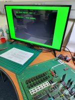
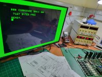
Programmed 2 new BASIC 2 ROMs into 2532As and voila!! She's alive!! Running for the first time without being on life support!

2001 Working-01.jpg

2001 Working-02.jpg

To say, I'm rather chuffed would be an understatement. My first 2001 is working! :)

To get to this point, replaced:

- CPU socket
- 2 x 2114 VRAM
- 1 x 74LS08 (C6)
- 2 x '244 buffers (likely not faulty)
- 16 x 2114 system RAM
- 6522 VIA
- All ROMs

Next will be to test the Cassette and IEEE ports. And, the keyboard and monitor........
 
Last edited:
Wow, that was a high 2114 mortality. Whatever problem they developed internally must have affected all of them at around the same age.

I'd caution against the TMS2532A. There has been a lot of talk on the Arcade game repair forums that they are difficult to program. In the case of the GQ-4x programmer (the one I have) it cannot program the 2532A directly. You can make it do it by setting it for 2732A to get the correct programming voltage and making an adapter socket, but that is a pest.
I suspect the issue with the 2114s is that they were MOS chips. When repairing Commodore computers (like the C64) and you find a MOS copy of a chip, it's 99% sure to be dead. I've not seen MOS 2114s before, but won't be surprised if they suffered from the same quality issue. To have 16 out of 16 fail is quite a thing but they're confirmed dead.

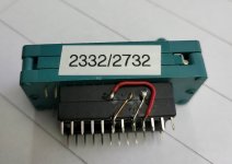
In terms of writing 2532As, I use this adaptor and select it as a TI 2732A and it works fine.

2532-2732 Adaptor.jpg
PS. The label should say 2532/2732 - a 2332 needs pin-21 strapped high to be read.
 
Back
Top