I have attached the most simple unit I could design and it be reliable and predictable.
(I designed other units with two mosfets that also worked well but it used more parts, and I think somehow the original unit would not have had these, so I am just presenting the one design to avoid any confusion).
It may well be deceptively simple.
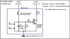
One of the interesting challenges with this one is to make a design that works with a paucity of available electrons and keep isolation between the DIAG & /RESET lines (I know Daver2 was concerned about that too).
The only current that can be sourced to charge capacitors and power the circuit is from the /RESET line and the DIAG line.
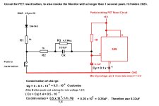
I decided the best way to do it was to use the current in the reset line, when the Reset button was closed, to accumulate charge on a large value capacitor.
The total stored charge, when the button is pressed for an indefinite period is limited by the uF value of the capacitor and the terminal voltage, which is limited to 0.95v by the series combination of a normal 1N4004 diode and a common garden 1N5819 schottky diode. Anywhere above 1.2v low on the Reset line, the reset starts to become unreliable. While a resistor could have been used instead of the diodes, it would not allow for different pull up resistor values that might be in different PET's, mine has a 470 Ohm but they might be 1k on some PETs. The diodes ensure the circuit works regardless of the exact pullup resistor value.
The base-emitter junction voltage drop of the transistor is used as the "comparator" . It is important that the capacitor is able to charge up to 0.95v, which is above above the the transistor's approximately 0.6V B-E threshold voltage, so that when the button is released (after is is held down for > 0.35 sec) there is still current flowing into the transistor's base circuit, so that its collector voltage is stable and low to control the DIAG line. In this minimal condition, or threshold area, the collector voltage stays low for around 40mS after the button is released, so the the DIAG line is held low and stable when the PET comes out of reset initiating the Monitor. If the button is held low indefinitely (or for many seconds at least), the maximum stored charge results in the DIAG line being low for about 0.4 sec after the button is released.
In the region below 0.35 seconds of a button push the transistor has not been pushed into conduction yet and the DAIG line remains high, so a short button push results in the PET resetting to BASIC.
I found this figure of around 0.35 seconds, on practical testing, to be good for discriminating between a long and short push, but you can double up on that to around 0.7sec simply by doubling the capacitor value if you wanted but I think that is a little long.
To an extent at least, this sort of circuit; its exact threshold of operation is affected a little by the transistor's hfe. I tried 3 different types of Silicon NPN signal transistors and they all performed the same with my PET. The BC107A is easy to get in the UK and the 2N3904 & 2N2222A easy to get in the USA. Watch out though, the 2N3904 has a different pinout. In the simulator testing it was modeled as a BC338 with a collector load of 1k. I built it first and when the design was perfected, I put it in the simulator later to find out the exact timing threshold.
The resistor in series with the transistor's collector is just a little insurance in case the PIA pin somehow got deployed high as an output when the transistor was conducting.I'm not sure if that can happen, but the resistor doesn't hurt.