I'm fairly certain if I have a proper composite circuit it'll work with this monitor just fine I'm not worried about an NTSC vs PAL issue I already know the monitor is NTSC as I've tested it with other NTSC composite sources.
Taking a look here I think what I want is probably
sjg-edit-80-b-ntsc (2017-09-21).bin because it's an 80 column (8032) and it has the business keyboard.
As for the circuit I've seen probably about 4 or 5 different versions and they all are slightly different.
For example this one which I took from
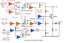
this video:
View attachment 1251589
shows the video signals being sourced from J1 with pins 1, 4, and 6 as ground whereas
on my PET I would be sourcing the signals from J7 with pins 2, 4, and 7 as ground so already I'm skeptical that this schematic would be compatible with my pet.
The one on the
aforementioned post shows the video coming from J3 and I'm not at all certain what's going on with J6 or a DIN connector.
And even this
one which I mentioned earlier looks pretty good except I don't understand why the video signals are coming from a DB9.
That last one is noted to have come from an article in a newsletter from the "Commodore PET Users Club of England" and some other page (which I can't find anymore) also referenced that same newsletter saying "...as found on the internet..." well I haven't been able to find that newsletter but I wish I could so I could read the whole thing rather than just having the schematic.
What I would like is a little more detail about building the circuit, specifically for my PET (an 8032 with a CTRC) and even more specifically with the goal of an NTSC composite output.
Like the schematic is great but also it would be nice if I could find what changes need to be made to the hardware of the PET (adding jumpers, cutting traces, whatever) and software (ROM changes) to make it all work.
There's a fair bit of information out there but there's a lot of variations of the circuit (probably due to variations in the PET itself, and also the PAL vs NTSC thing) but so far all of the schematics I've seen are just kind of presented as "well here it is, this is the PET composite circuit" rather than "this is *A* PET composite circuit for *THIS TYPE OF PET* and with *THIS VIDEO STANDARD* as a result. So ... a lot of guesswork on my part.
Example
from here:
What "standard" PAL or NTSC and which PET? Well considering it came from the "Pet users club of England" probably PAL.
")